D1 Servo Drive User Manual Servo Drive Configuration
HIWIN MIKROSYSTEM CORP. 5-47
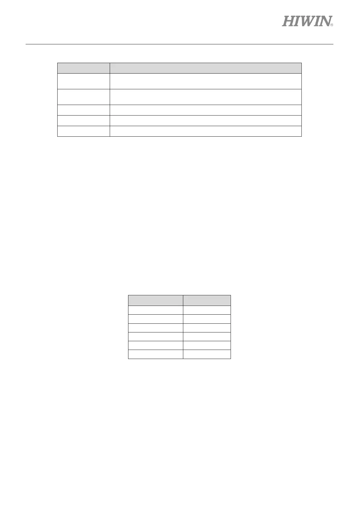
Table5.5.1
Motor will be regarded as in-position after position error is within
target radius. The default value is 100 times of encoder resolution.
Position error needs to be within target radius for the set debounce
time for motor to be regarded as in-position.
Sum of move time and settling time
◼ Debounce time setting
In-position signal could be unstable as the motor may overshoot during positioning. In this case, user
can set debounce time to have stable in-position signal. In-position signal will only be sent after
position error is within the target radius for the set debounce time. The larger the debounce time is,
the more stable the in-position signal is. But setting larger debounce time could have longer time
delay. Users can set appropriate debounce time by observing in-position signal in oscilloscope. For
finding appropriate debounce time, please refer to below.
(1) Set Target radius and set Debounce time to 0 ms. Let the motor move for a period of time and
observe in-position signal from oscilloscope, as figure 5.5.2. When the motor is in-position,
in-position signal is at high level. In figure 5.5.2, there are six protruding pulses as the motor
moves close to the target position. Observe the time duration of protruding pulse.
Table 5.5.2