D1 Servo Drive User Manual Tuning
HIWIN MIKROSYSTEM CORP. 6-5
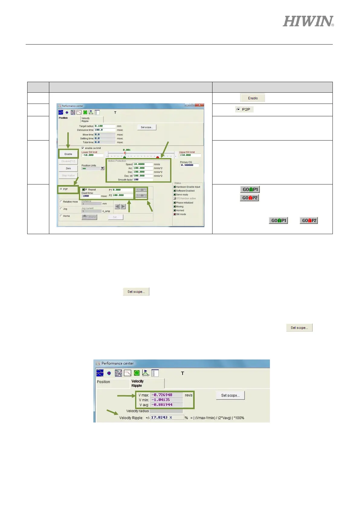
Below is the example of performing test run by point-to-point (P2P) motion.
Table6.2.1
Click on to enable the motor.
Set P1 and P2. (If software limits are used,
ensure P1 and P2 are within Lower SW
limit and Upper SW limit.
Set the desired speed, acceleration,
deceleration and smooth factor (Refer to
section 3.4.) in Motion Protection area. If
user has no special requirement, test run
can be performed by using the default
values.
Click on , the motor moves to P1.
Click on , the motor moves to P2. If
repeated point-to-point (P2P) motion is
required, select Repeat and set dwell
time. Then click on or to
perform point-to-point (P2P) motion.
Settling time can be measured in Performance center. Target radius and debounce time can also be set
in Performance center, please refer to section 5.5. During motion, primary CG can be adjusted to meet
the requirement of settling time. Higher servo gain can have faster response and shorter settling time.
User can observe the required time for entering target radius by move time, settling time and total time.
(Refer to section 3.7.) Click on to show Scope to observe the waveforms related to settling
time. Velocity ripple can be measured in Performance center. User can observe velocity ripple by
point-to-point (P2P) motion. V max, V min, V avg and Velocity Ripple show the maximum speed,
minimum speed, average speed and velocity ripple of a constant speed phase. Click on button
to show Scope to observe the waveforms related to velocity ripple.
Figure 6.2.2 Performance center-Velocity Ripple page