D1 Servo Drive User Manual Servo Drive Configuration
HIWIN MIKROSYSTEM CORP. 5-17
Figure5.2.2.3.2
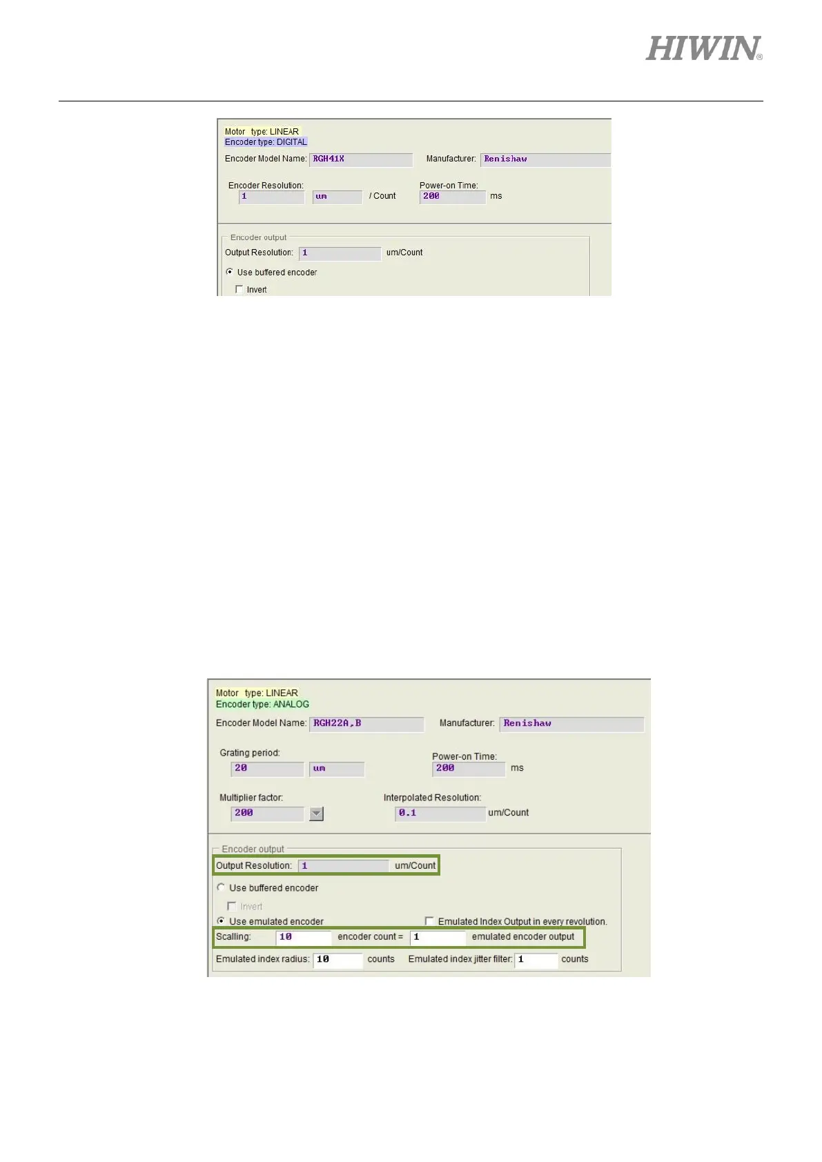
(2) Emulated encoder output
When emulated encoder output is selected, the signals received from encoder will be scaled before
the signals are output to controller. In some cases, such as when controller cannot receive encoder
signals sent at high frequency, the scaling can be set to 10:1 to let ten encoder counts equal one
emulated encoder output. When the multiplier factor of analog encoder is set to a high value, scaling
can also be used to lower the output resolution. If the scaling is set to 1 encoder count = -1 emulated
encoder output, the direction will be reversed. For instance, in figure 5.2.2.3.3, the grating period of
analog encoder is 20 um and the interpolated resolution after setting the multiplier factor to 200 is 0.1
um/count. If the scaling is set to 10 encoder counts = 1 emulated encoder output, the output
resolution becomes 1 um/count.
Note:
Emulated encoder output is not available while saving parameters to Flash.
Figure5.2.2.3.3