10. Frequency Response Adjustment
Equipment
Synthesized Sweeper
...........................................
HP
8340A/B
Measuring Receiver..............................................
HP 8902A
Power Sensor...................................................
HP 8482A
Power Splitter
..................................................
HP 11667A
Adapters
Type N (m) to Type N (m)
........................................
1250-1475
Type N (f) to APC 3.5 (m)
........................................
1250-1750
Type APC 3.5 (f) to APC 3.5 (f)
...................................
5061-5311
Cables
BNC,122cm
(48in)............................................
HP 10503A
APC
3.5,91cm(36in)
. . . . . . . . . . . . . . . . . . . . . . . . . . . . . . . . . . . . . . . . ...8120-4921
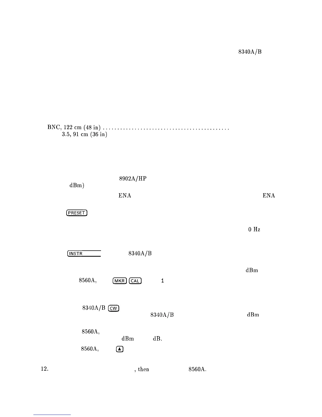
Procedure
1. Connect the equipment as shown in Figure 2-13. Do not connect the HP 8482A Power
Sensor to the HP 11667B Power Splitter.
2. Zero and calibrate the HP
8902A/HP
8482A
combination in log mode (power levels read
out in
dBm)
and connect the power sensor through an adapter to the power splitter.
3. Place the WR PROT/WR ENA jumper on the A2 Controller assembly in the WR ENA
position.
4. Press
[PRESET)
on the HP 8560A and set the controls as follows:
CENTERFREQ
. . . . . . . . . . . . . . . . . . . . . . . . . . . . . . . . . . . . . . . . . . . . . ..lO MHz
SPAN
. . . . . . . . . . . . . . . . . . . . . . . . . . . . . . . . . . . . . . . . . . . . . . . . . . . . . . . . . . . OHz
RES BW
. . . . . . . . . . . . . . . . . . . . . . . . . . . . . . . . . . . . . . . . . . . . . . . . . . . . . 300kHz
dB/DIV
. . . . . . . . . . . . . . . . . . . . . . . . . . . . . . . . . . . . . . . . . . . . . . . . . . . . . . . . . 2dB
5. Press
@NSTR
PRESET) on the HP
8340A/B
and set the controls as follows:
CW . . . . . . . . . . . . . . . . . . . . . . . . . . . . . . . . . . . . . . . . . . . . . . . . . . . . . . . . . ..lO MHz
POWERLEVEL
. . . . . . . . . . . . . . . . . . . . . . . . . . . . . . . . . . . . . . . . . . . . . . -4
dBm
6. On the HP 8560A, press
IhnKR)
ICAL)
MORE
1
OF 2 SERVICE CAL DATA, then FLATNESS.
The current value of the RF Gain DAC should be displayed in the active function area.
7. Enter the appropriate Power Sensor Calibration factor into the HP 8902A.
8. Set the HP
8340A/B
[cw)
output to the frequency indicated in the active function area of
the HP 8560A display. Adjust the HP
8340A/B
POWER LEVEL for a -10
dBm
reading
on the HP 8902A.
9. On the HP
8560A,
adjust the RF Gain DAC value using the front-panel knob or keypad
until the marker reads -10
dBm
+/-.10 dB.
10. On the HP 8560A, press
II)
to proceed to the next frequency.
11. Repeat steps 7 through 10 for all low band frequencies.
12. Press PREV MENU STORE DATA
,then
YES on the HP
856OA.
2-46 Adjustment Procedures