EasyManuals Logo
Home>Hypertherm>Control Systems>MicroEdge

Hypertherm MicroEdge User Manual

Hypertherm MicroEdge
574 pages
To Next Page IconTo Next Page
To Previous Page IconTo Previous Page
Page #505 background imageLoading...
Page #505 background image
DXF Import 481
Example:
+ +
+ +
1 2
3 4
5
If the Lead-in and Lead-out were made up as additional line segments added to the top and side line
segments, additional text would be required to indicate which direction the next line segment should
take as part of the part program.
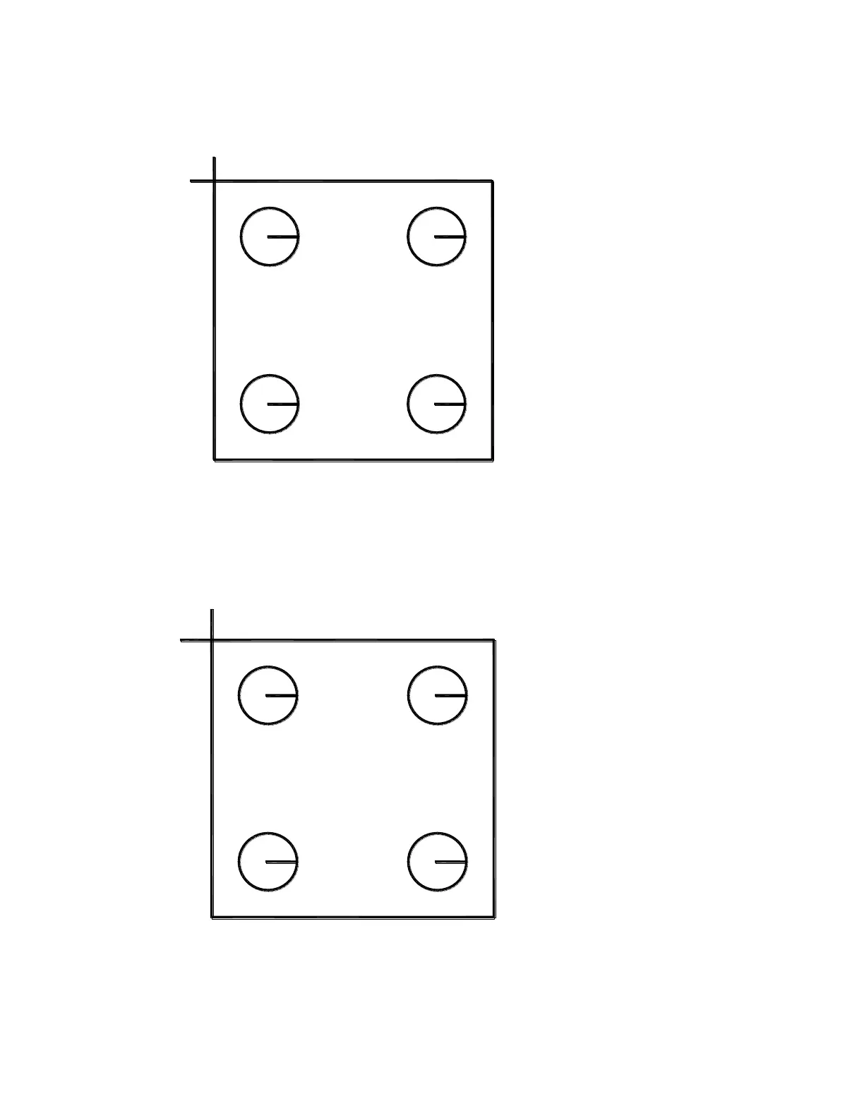
Example:
+ +
+ +
1 2
3 4
R5
In this example, the Letter “R” has been snapped to the intersection of the four line segments to
indicate that the next line segment after Lead-in (pierce 5) would be the segment which is located at
350 to 10 degrees and then to the other connected segments on the square. After the left side
(vertical) cut segment has been executed, no additional text is required to indicate which line should

Table of Contents

Other manuals for Hypertherm MicroEdge

Questions and Answers:

Question and Answer IconNeed help?

Do you have a question about the Hypertherm MicroEdge and is the answer not in the manual?

Hypertherm MicroEdge Specifications

General IconGeneral
BrandHypertherm
ModelMicroEdge
CategoryControl Systems
LanguageEnglish

Related product manuals