3.7 Address Configuration
A3-42
ME0384-4A
■
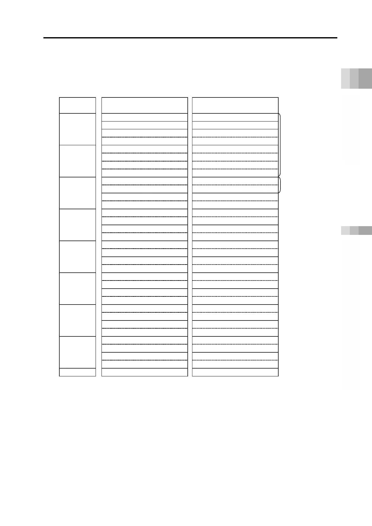
PROFINET-IO overall address configuration example (positioner 2 mode + EC Connection Unit)
This is an example for connection of 12 axes of Positioner 2 axes and one unit of the EC
connection unit (for four axes).
RCON
PLC input
4-word
Module count
High byte Low byte High byte Low byte
1
Power supply unit status signal 0
Power supply unit status signal 1
2
(Not available)
Power supply unit status signal 2
Power supply unit status signal 3
Power supply unit status signal 4
3
(Axis 0) Command position No.
(Axis 0) Completed position No.
2 words each
(Axis 1) Command position No.
(Axis 1) Completed position No.
4
(Axis 2) Command position No.
(Axis 2) Completed position No.
(Axis 3) Command position No.
(Axis 3) Completed position No.
5
(Axis 4) Command position No.
(Axis 4) Completed position No.
(Axis 5) Command position No.
(Axis 5) Completed position No.
6
(Axis 6) Command position No.
(Axis 6) Completed position No.
(Axis 7) Command position No.
(Axis 7) Completed position No.
7
(Axis 8) Command position No.
(Axis 8) Completed position No.
(Axis 9) Command position No.
(Axis 9) Completed position No.
8
(Axis 10) Command position No.
(Axis 10) Completed position No.
(Axis 11) Command position No.
(Axis 11) Completed position No.
(Axis 12 to Axis 15) Control signal
(Axis 12 to Axis 15) Status signal
*1 The EC connection unit occupies domains and axis numbers for four axes (one word) even though
not all of four axes are connected.
The axis numbers for the EC connection unit should be assigned from after axes connected to
driver units (RCON-PC/AC/DC/PC/SC) and SCON extension unit.

 Loading...


