4.4 Part Names/Functions and External Dimensions
A4-10
ME0384-4A
Chapter 4 24V Driver Unit EC Connection Unit
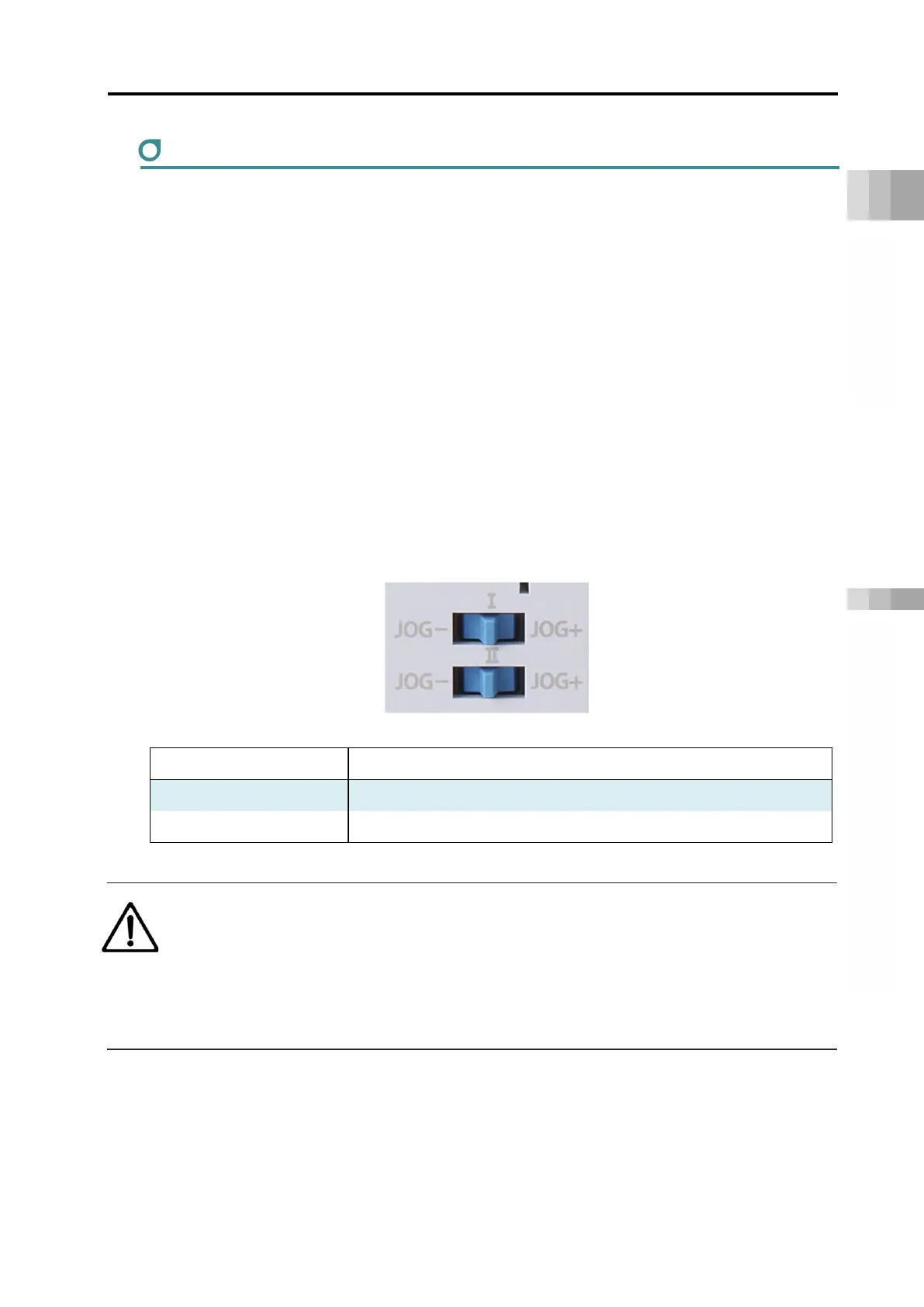
Jog switch
A switch for jog operation. I indicates the 1st axis, and II indicates the 2nd axis.
Tilt the switch to the JOG+ side to perform jog operation in the + direction, and to the JOG- side
for jog operation in the - direction. Tilting the switch further increases the jog speed step by step.
However, if home return is not complete, the jog speed will be home return speed.
When performing jog operation with the JOG switch with servo ON, the servo will be ON even
after completion; with servo OFF, perform jog operation after servo ON and the servo will be
OFF after completion.
Note that the operation of the jog switch is enabled only in MANU teaching mode. It is disabled
in MANU monitor mode and AUTO mode.
The jog switch is also disabled when opening the screen in which the actuator can be operated
with the teaching tool. When opening the screen in which operation can be done with the jog
switch, the actuator will decelerate and stop.
If parameter No. 194 "JOG Switch" is set to "1", this switch will be enabled (Initial setting is “0:
Valid”.)
Symbol Description
JOG+ Jog operation in + direction (home reverse direction)
JOG- Jog operation in - direction (home direction)
Caution
● The jog switch is disabled when the communication with the teaching tool is
disconnected while the screen in which the actuator can be operated with the teaching
tool is opened.
● To enable jog switch operation again, turn the RCON system on again or perform
software reset.

 Loading...


