4.4 Part Names/Functions and External Dimensions
A4-24
ME0384-4A
Chapter 4 24V Driver Unit EC Connection Unit
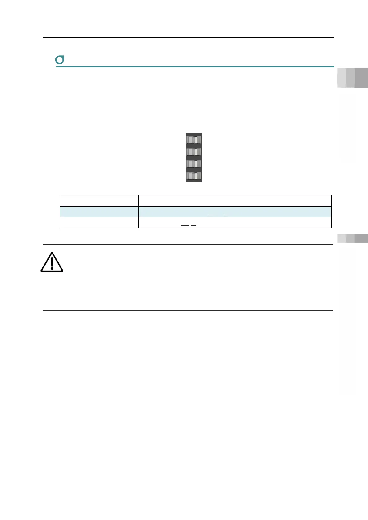
Brake release switch
They are switches to release the brake compulsorily. It comes the switches for 1st, 2nd, 3rd and
4th axes from the top.
Should be on NOM side during normal operation. On NOM side, the brake will be released by
servo ON and locked by servo OFF. On RLS side, there will be forced release regardless of
servo ON/OFF (except when control power is OFF).
Symbol Description
RLS Brake release (Brake Release)
NOM Brake lock (Normal)
Warning
● Be careful when releasing the brake. Releasing carelessly may cause injury or damage
to the actuator body, workpiece or surrounding devices due to the slider or rod falling.
● After releasing the brake, be sure to return the brake to the enabled status. It is very
dangerous to operate with the brake released. It may cause injury or damage to the
actuator body, workpiece or surrounding devices due to the slider or rod falling.
RLS
NOM

 Loading...


