3.8 I/O Signals
A3-90
ME0384-4A
3.8 I/O Signals
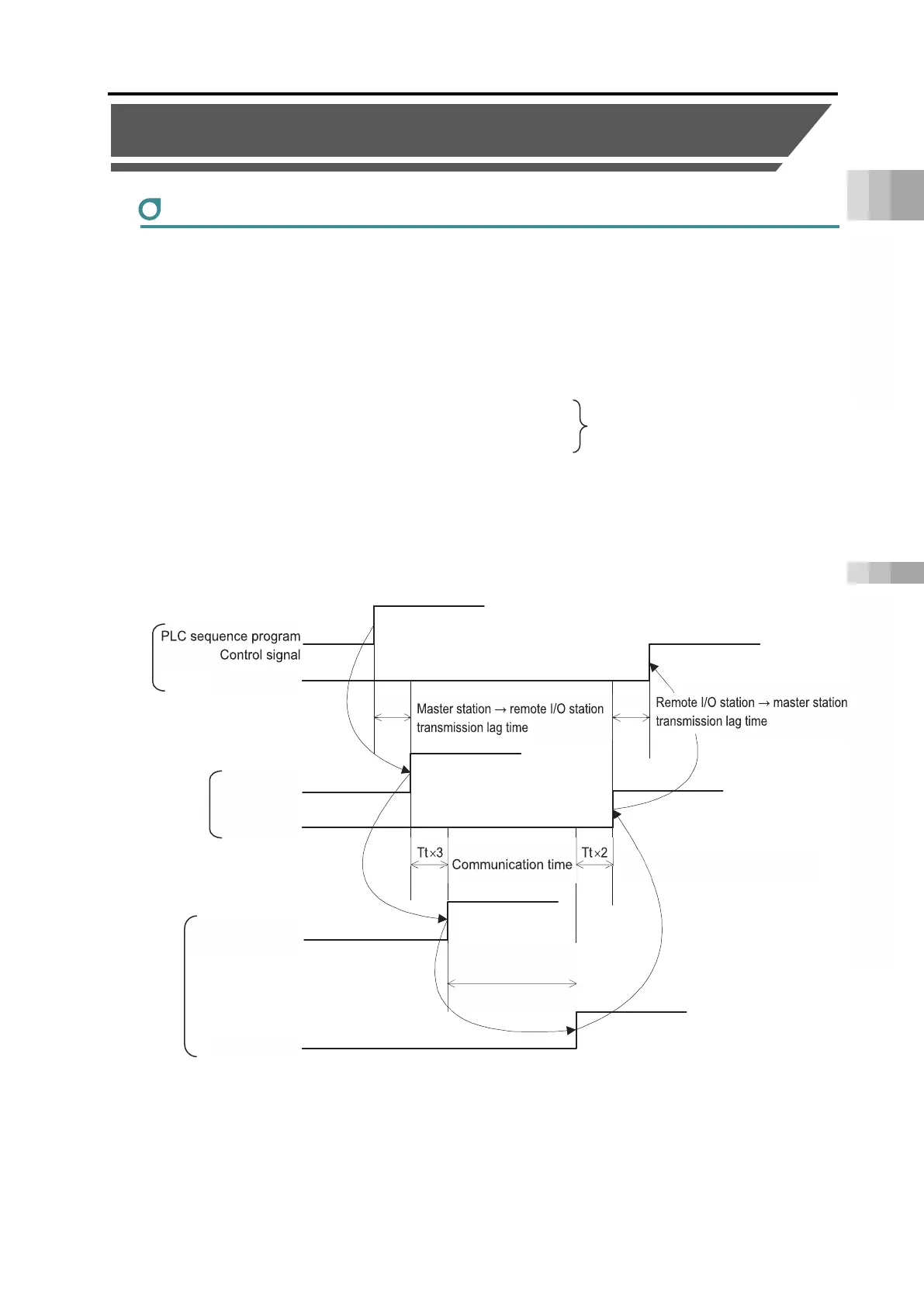
Timing of I/O signals
In order to operate the actuator with a PLC sequence program, various control signals are
turned ON; the maximum response time until their response (status) signals return to the PLC is
expressed with the following formula.
The PLC is the master station and the gateway unit the remote I/O station.
Maximum response time (ms) = Yt + (Tt × 3) + command processing time + (Tt × 2) + Xt
Tt =
Transmission time: 1 to 4 axes 1ms, 5 to 9 axes 2ms, 10 to 14 axes 3ms, 15 to 16 axes 4ms
Yt :
Master station → remote I/O station transmission lag time
Xt :
Remote I/O station → master station transmission lag time
For the transmission lag time from the master station to the remote I/O station (Yt) and from the
remote I/O station to the master station (Xt), refer to the instruction manuals for the field network
master units and mounted PLC.
Also, refer to “Caution when Connecting EC Connection Unit (Pg. A3-117)” when the EC
connection unit is to be connected.
If a communication error occurs for such a reason as a problem on the transmission path, the
duration of communication time (Tt × 3 / Tt × 2) should be extended for amount of Transmission
Time (Tt) × Number of Error Occurrence Times.
If communication cannot be normally performed, an operation cancel level alarm (alarm code
8DE "Driver unit communication error") is generated, and the actuator stops.
Status signal
Driver unit
Control signal
Command
processing time
Yt Xt
Field network transmission lag time

 Loading...


