EasyManua.ls Logo

IAI Rcon - Positioner 3 Mode Assignment

IAI Rcon
838 pages
To Next Page IconTo Next Page
To Previous Page IconTo Previous Page
Loading...
3.7 Address Configuration
A3-78
ME0384-4A
Chapter 3 Gateway Unit
Specifications Section
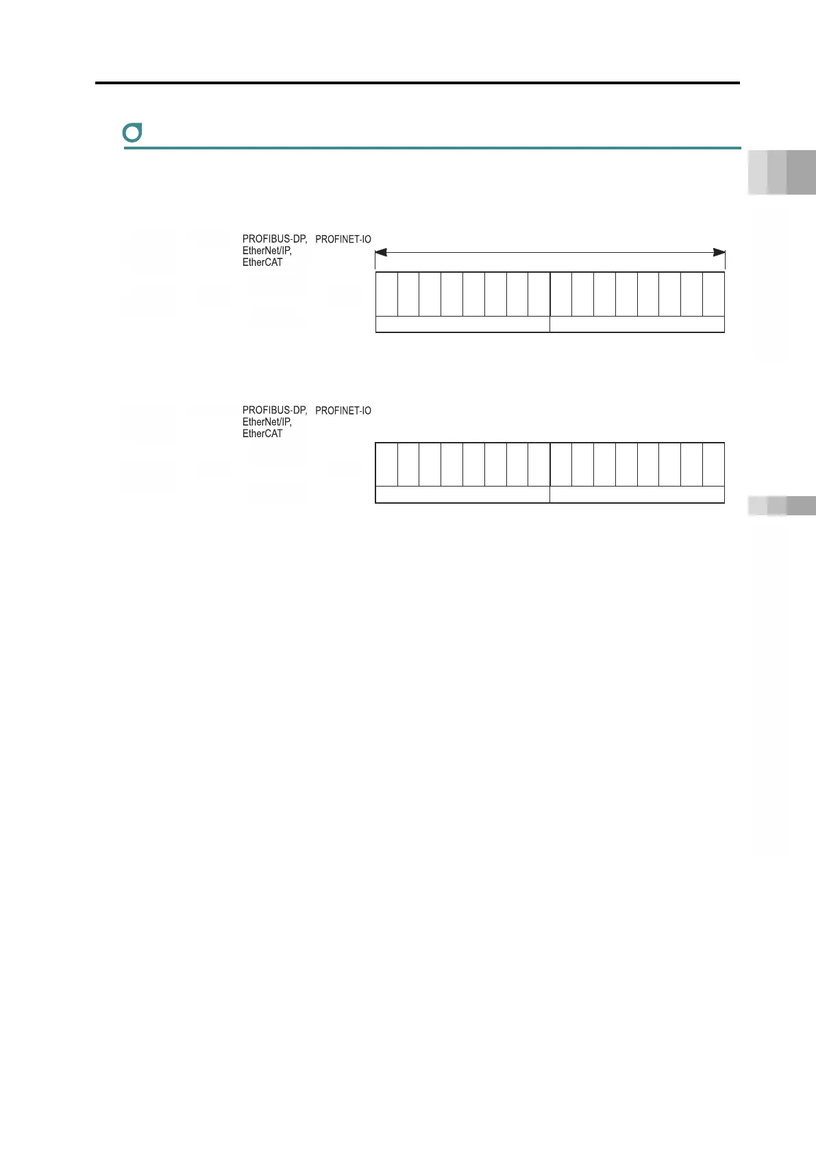
Positioner 3 mode assignment
Assigning the positioner 3 mode is as follows.
PLC output = Axis control signal
Address
*
PLC input = Axis status signal
Address
*
* m is the head register address of each axis. n is the head relative address of each axis.
p is the head module address of each axis.
CC-Link, CC-Link IE Field, and DeviceNet have word addresses, PROFIBUS-DP, EtherNet/IP, and
EtherCAT use byte addresses, and PROFINET-IO uses 4-word module addresses.
b15
b14
b13
b12
b11
b10
b9 b8 b7 b6 b5 b4 b3 b2 b1 b0
EMGS
ZONEI
PSFL
SV
ALM
MOVE
HEND
PEND
PM64
PM32
PM16
PM8
PM4
PM2
PM1
Status signal
Completed position No.
b15
b14
b13
b12
b11
b10
b9 b8 b7 b6 b5 b4 b3 b2 b1 b0
BKRL
SON
RES
STP
HOME
CSTR
PC64
PC32
PC16
PC8
PC4
PC2
PC1
Control signal
Command position No.
1 word = 16 bits
CC-Link,
CC
-
Link IE
Field
RWw
m + 0
n + 0
(High byte)
n + 0
(Low byte)
n + 1
DeviceNet
p+0
CC-Link,
CC
-
Link IE
Field
RWr
m + 0
n + 0
(High byte)
n + 0
(Low byte)
n + 1
DeviceNet
p+0

Table of Contents

Related product manuals