2.3 Specifications
A2-25
ME0384-4A
Chapter 2 System Configuration and Specifications
Unit connection restrictions
The RCON system has the following restrictions.
Check the following descriptions and then make a selection for each unit.
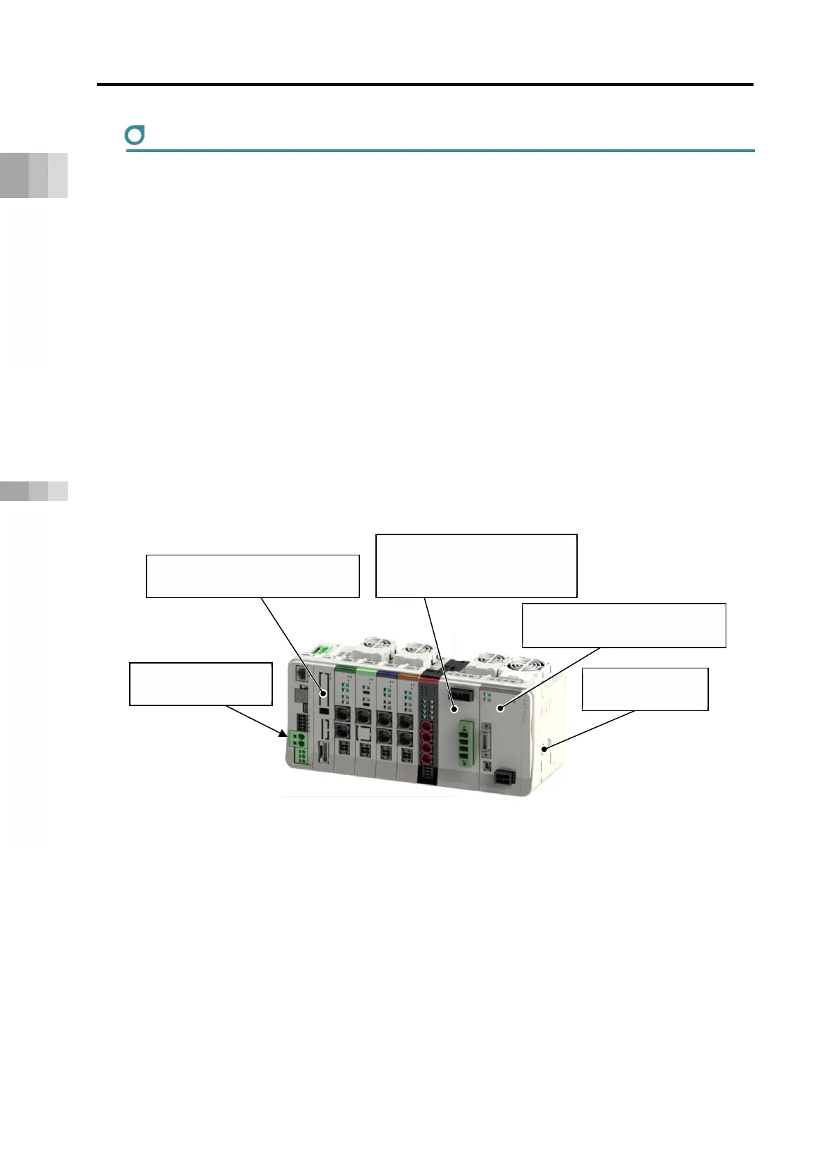
(1) Unit arrangement
RCON System possesses a locking structure with unit linking system. Units available for linking
to each other have the same connectors, and they can be laid out freely. However, the
arrangement of the following units is restricted.
Gateway unit: Placed on the far left of the RCON system.
Terminal unit: Placed on the far right of the RCON system.
200V Power Supply Unit : Install on the right side of the 24V driver unit (RCON-PC/AC/DC)
and the EC connection unit, or gateway unit if there is no 24V
driver unit or EC connection unit.
200V Driver Unit : Install on the right side of the 200V power supply unit.
SCON Extension unit : Connected to the right of the gateway unit.
Gateway unit, SCON extension unit and terminal unit can only be linked to one unit for each set
of the systems.
SCON Extension unit
(connected to right of gateway unit)
Gateway Unit
(Installed at left end)
Terminal unit
(placed on far right)
(Installed on right of 24V Driver
Unit and EC Connection Unit)
200V Driver Unit (Installed on
right of 200V power supply unit)