2.5 Connection Diagrams
A2-49
ME0384-4A
Chapter 2 System Configuration and Specifications
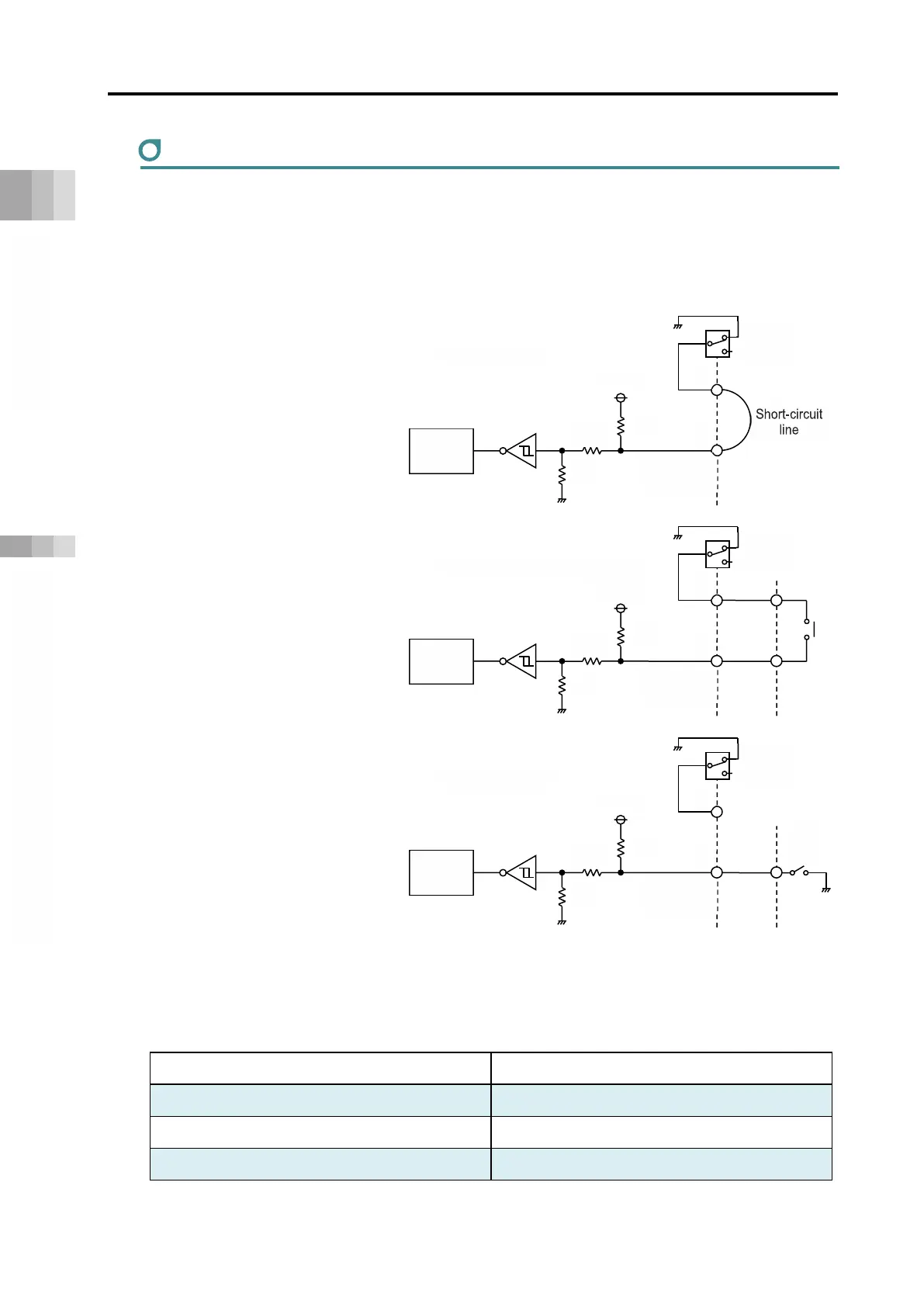
AUTO/MANU mode switching circuit wiring
You can also switch AUTO/MANU by connecting the PLC/contact to the AUTO/MANU
(automatic/manual operation) input of the system I/O connector of the gateway unit.
There are 3 types of AUTO/MANU mode switching circuit,as shown below.
(1) Switch only
The configuration is such that
the AUTO/MANU input (3, 8-
pin) in the system I/O
connector is short-circuited with
a short-circuited line and
switched only with the switch.
(2) Switch and external contact
Connect the switch and
external contact in series as
shown in the figure. It is AUTO
if both are connected and
MANU if one is open.
(3) External output
Connect the AUTO/MANU
signal input 3-pin in the system
I/O connector to the PLC, etc. It
is AUTO at PLC I/O output ON
(0 V) and MANU at OFF
(open).
In this case, the AUTO/MANU
switch will be disabled.
Note that the specification of the system I/O connector is as follows.
Item Specifications
Input current 5mA
Leakage current Max. 1 mA
Isolation method Non-isolated
Internal
circuit
AUTO
MANU
VP24
5.6k
[Switch and external contact]
8
3
Internal
circuit
AUTO
VP24
100k
20k
Internal
circuit
AUTO
VP24