3.7 Address Configuration
A3-30
ME0384-4A
3.7 Address Configuration
The RCON address configuration is the same for all driver units regardless of field network type.
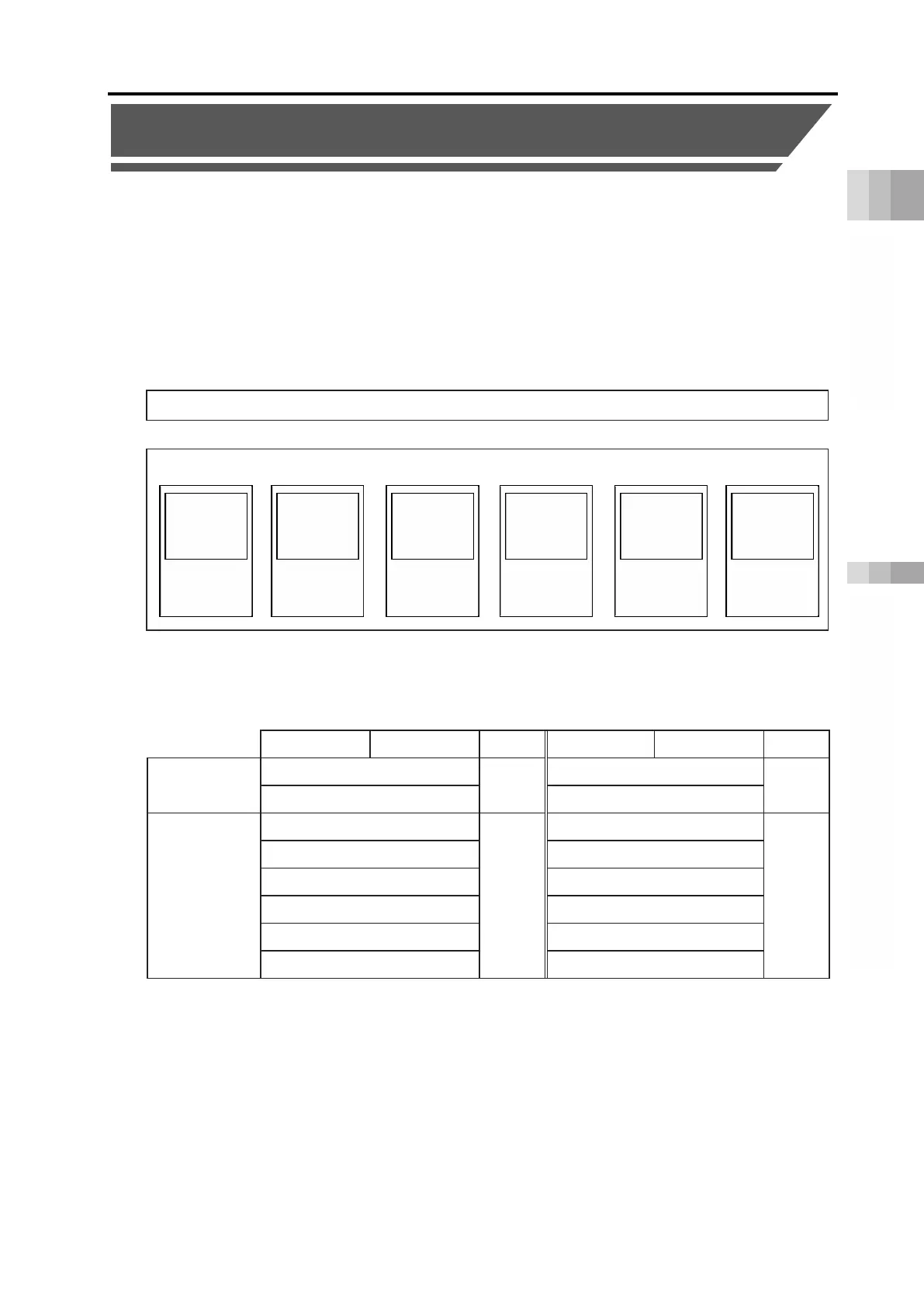
The addresses occupied by the network consist of eight words of the fixed domains, data
domains that vary depending on the operation mode and number of axes and the data domains
for the EC connection unit. Each operation mode and occupied data region is as follows.
Direct numerical control mode, simple direct mode and positioner 1~3 and 5 modes can be
mixed for use and the model for each axis can be selected arbitrarily.
It is not available to select an operation mode in the EC connection unit.
(1) Fixed region configuration
PLC output ⇒ RCON
RCON ⇒ PLC input
High byte Low byte
Word count
High byte Low byte
Word count
Gateway
control region
Gateway control signal 0
2
Gateway status signal 0
2
Gateway control signal 1 Gateway status signal 1
Power supply
unit region
*
Not available.
6
Power supply unit status signal 0
6
Not available.
Power supply unit status signal 1
Not available.
Power supply unit status signal 2
Not available.
Power supply unit status signal 3
Not available.
Power supply unit status signal 4
Not available.
Not available.
* Occupied as a data region even if a power supply unit is not connected.
+
Fixed region (8-word)
Data region
+
Positioner 2, 5
mode
(2-word)
×
Number of Axes
+ +
+
Positioner 3
mode
(1-word)
×
Number of Axes
numerical
control mode
(8-word)
×
Number of Axes
numerical
control mode
(4-word)
×
Number of Axes
Positioner 1
mode
(4-word)
×
Number of Axes
Connection
Unit
(1-word)
×
Number of Unit
+

 Loading...


