3.7 Address Configuration
A3-31
ME0384-4A
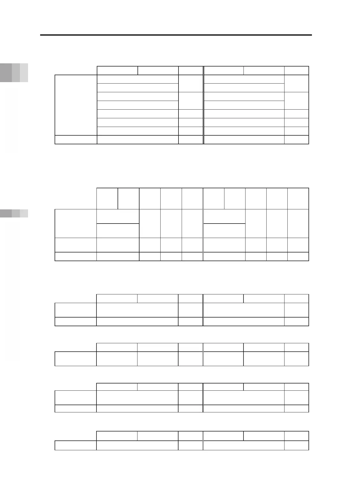
(2) Direct numerical control mode data region configuration
PLC output
each axis input Each axis output
PLC input
High byte Low byte
Word count
High byte Low byte
Word count
Direct
specified
region
Specified position data (L)
*
2
Present position data (L))
*
2
Specified position data (H))
*
Present position data (H))
*
Specified positioning width (L))
*
2
Present current value (L))
*
2
Specified positioning width (H))
*
Present current value (H))
*
(Note 1)
Specified acceleration/deceleration
Pushing current limit value
*(L) is the low word of a 2-word datum while (H) is the high word of a 2-word datum.
Note 1:
The present current value should be the command current value for the stepper motor and be the
feedback current value for the AC servomotor (including AC servomotor connected to SCON-CB).
(3) Simple direct mode and positioner 1 mode data region configuration
PLC output ⇒ each axis input
Each axis output ⇒ PLC input
High
byte
Low
byte
Word
count
direct
1 mode
High
byte
Low
byte
Word
count
direct
1 mode
Position data
specified
region
Specified
position data (L)
2 ○ x
*
Present position
data (L)
2 ○ ○
Specified
position data (H)
Present position
data (H)
Position
specified region
1 ○ ○
1 ○ ○
* Positioner 1 mode does not use the position data specified region (PLC ⇒ each axis input),
but it is occupied as a data region.
(4) Positioner 2 mode data region configuration
Position
specified region
Command position No. 1 Completed position No. 1
Control signal region
Control signal 1 Status signal 1
(5) Positioner 3 mode data region configuration
Control signal region
Control signal
1 Status signal
1
(6) Positioner 5 mode data region configuration
Position
specified region
Command position No. 1
Present position data
(0.1 mm increments)
1
(7) EC connection unit data region configuration
High byte Low byte
Word count
High byte Low byte
Word count
Control signal (for four axes).
Status signal (for four axes)

 Loading...


