3.7 Address Configuration
A3-81
ME0384-4A
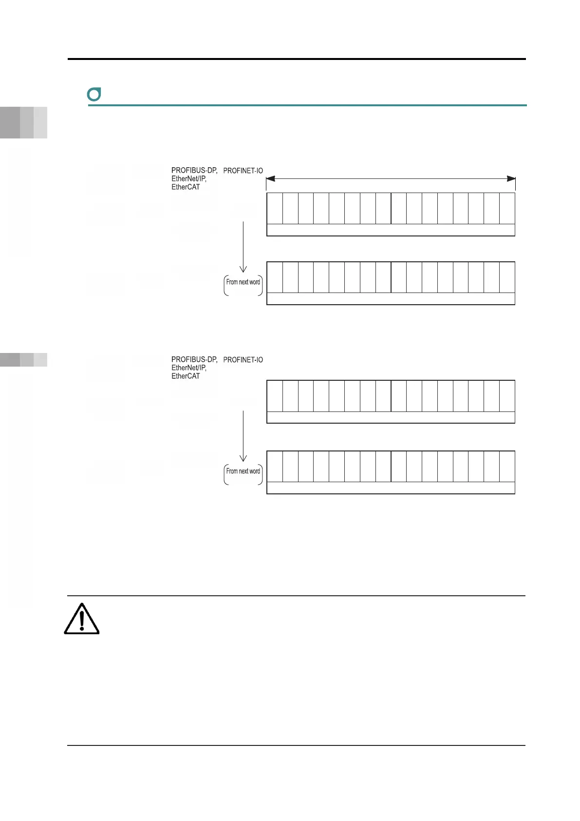
Positioner 5 mode assignment
Assigning the positioner 5 mode is as follows.
PLC output = Axis control signal
Address
*
PLC input = Axis status signal
Address
*
* m is the head register address of each axis. n is the head relative address of each axis.
p is the head module address of each axis.
CC-Link, CC-Link IE Field, and DeviceNet have word addresses, PROFIBUS-DP, EtherNet/IP, and
EtherCAT use byte addresses, and PROFINET-IO uses 4-word module addresses.
Caution
● The maximum present position data that can be output in positioner 5 mode is 3,276.7
mm (327.67° for DD motor).
● If the maximum value is exceeded, the present position data will not be correctly
output.
This may lead to display or operation malfunction, resulting in personal injury or device
damage.
● For use in an operation range exceeding the maximum value, select a different
operation mode.
b15
b14
b13
b12
b11
b10
b9 b8 b7 b6 b5 b4 b3 b2 b1 b0
-
-
-
-
-
-
-
-
-
-
-
-
-
-
-
-
-
-
-
SON
RES
STP
b15
b14
b13
b12
b11
b10
b9 b8 b7 b6 b5 b4 b3 b2 b1 b0
Present position data (signed integer)
PM8
PM4
PM2
PM1
SV
ALM
Status signal/completed position No.
-
RWw
RWw
-
RWr
RWr

 Loading...


