EasyManuals Logo

IAI Rcon User Manual

IAI Rcon
838 pages
To Next Page IconTo Next Page
To Previous Page IconTo Previous Page
Page #190 background imageLoading...
Page #190 background image
3.7 Address Configuration
A3-87
ME0384-4A
Specifications Section
Chapter 3 Gateway Unit
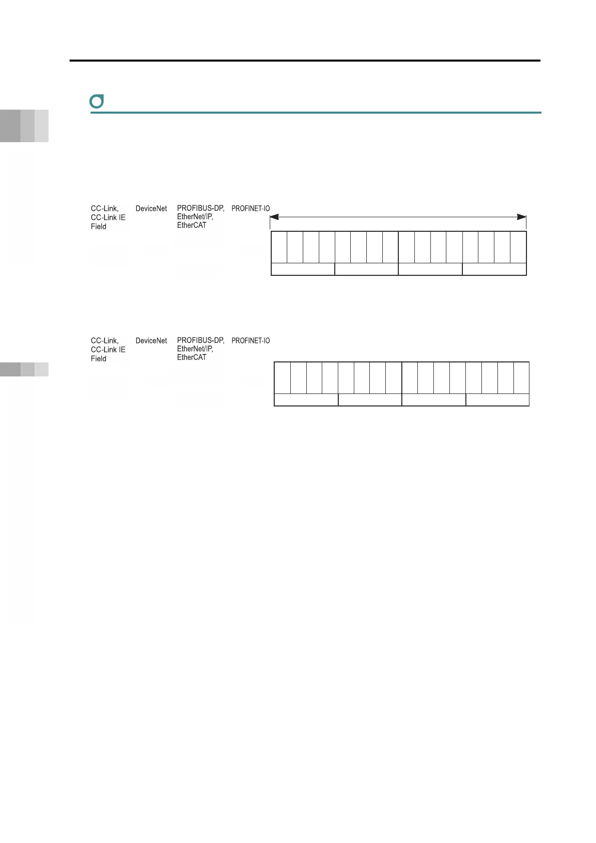
Assignment of EC Connection Unit
The assignment of the EC connection unit should be as shown below.
The EC connection unit occupies domains for four axes (one word) even though not all of four
axes are connected.
PLC output = Axis control signal
Address
*
PLC input = Axis status signal
Address
*
* m is the head register address of each unit. n is the head relative address of each unit.
p is the head module address of each unit.
CC-Link, CC-Link IE Field, and DeviceNet have word addresses, PROFIBUS-DP, EtherNet/IP, and
EtherCAT use byte addresses, and PROFINET-IO uses 4-word module addresses.
b15
b14
b13
b12
b11
b10
b9
b8
b7
b6
b5
b4
b3
b2
b1
b0
E3RD
*ALM
LS1/PE1
LS0/PE0
E2RD
*ALM
LS1/PE1
LS0/PE0
E1RD
*ALM
LS1/PE1
LS0/PE0
E0RD
*ALM
LS1/PE1
LS0/PE0
Status signal4th Axis
Status signal (3th Axis)
Status signal (2nd Axis)
Status signal1軸目)
b15
b14
b13
b12
b11
b10
b9
b8
b7
b6
b5
b4
b3
b2
b1
b0
RES
ST1
ST0
RES
ST1
ST0
RES
ST1
ST0
RES
ST1
ST0
control signal (4th Axis)
control signal (3th Axis)
control signal (2nd Axis)
control signal (1st Axis)
1 word = 16 bits
RWw
m0
n0
(High byte)
n0
(Low byte)
n1
p0
RWr
m0
n0
(High byte)
n0
(Low byte)
n1
p0

Table of Contents

Questions and Answers:

Question and Answer IconNeed help?

Do you have a question about the IAI Rcon and is the answer not in the manual?

IAI Rcon Specifications

General IconGeneral
BrandIAI
ModelRcon
CategoryController
LanguageEnglish

Related product manuals