3.7 Address Configuration
A3-48
ME0384-4A
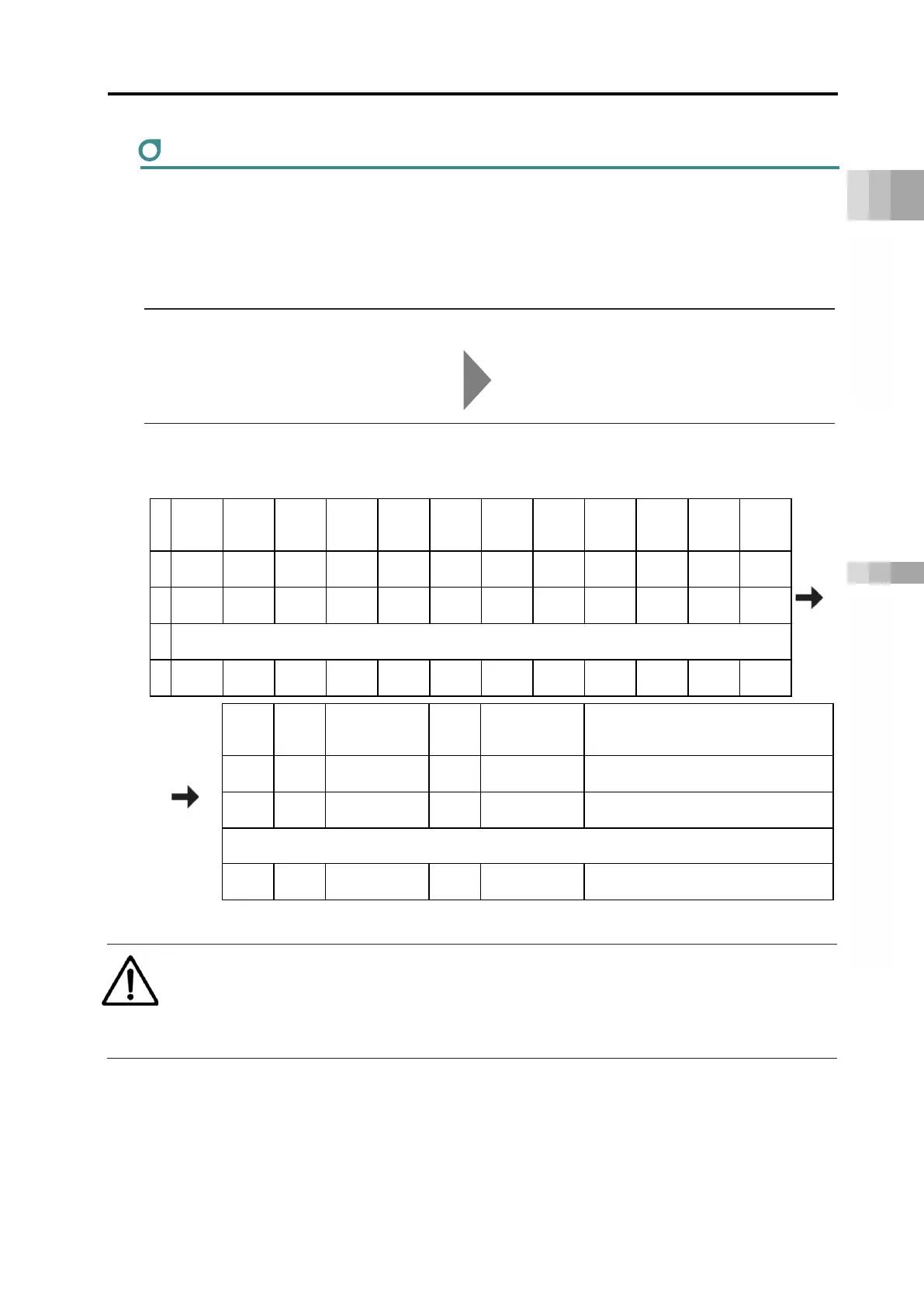
Position table
Each driver unit can operate in 6 types of modes, direct numerical control mode, simple direct
mode, positioner 1~3 and 5 modes, depending on the gateway unit.
Simple direct mode and positioner mode require the creation of a position table in advance,
using a teaching tool, in order to perform positioning.
Refer to "LECYLINDER Position Table (Pg. A3-84)" for the EC connection unit.
Reference
PC software operating method PC software (RCM-101-*-*) manual (ME0155)
Teaching pendant operating method Touch Panel Teaching Pendant manual
TB-02/02D(ME0355), TB-03(ME0376)
The position table is explained using a sample PC software screen.
(The displayed contents differ for teaching pendants)
No.
Position
[mm]
Speed
[mm/s]
Acceleration
[G]
Deceleration
[G]
Push
[%]
Threshold
[%]
width
Zone+
[mm]
Zone-
[mm]
deceleration
Incremental
Gain
set
0 0.00
100.00
0.30
0.30
0
0
0.10
0.00
0.00
0
0
0
1 100.00
100.00
0.30
0.30
0
0
0.10
0.00
0.00
0
0
0
2 1-line comment can be input
3
Stop
Mode
damping
torque limit
Connected
No.
Wait time
[s]
Comment
0
0
100
1
10.00
Test 1
0
0
100
0
5.00
Test 2
Caution
● When using the rotary type or gripper type, be sure to confirm the following.
"3.8 Precautions for Rotary Type (page A3-148)"
"3.8 Precautions for Gripper Type (page A3-151)"