3.8 I/O Signals
A3-91
ME0384-4A
Function of I/O signals
I/O signals are prepared for each axis No.
ON means that the corresponding bit is "1" and OFF means the corresponding bit is "0".
Refer to "Features of Input and Output Signals for EC Connection Unit (Pg. A3-114)" for the EC
connection unit.
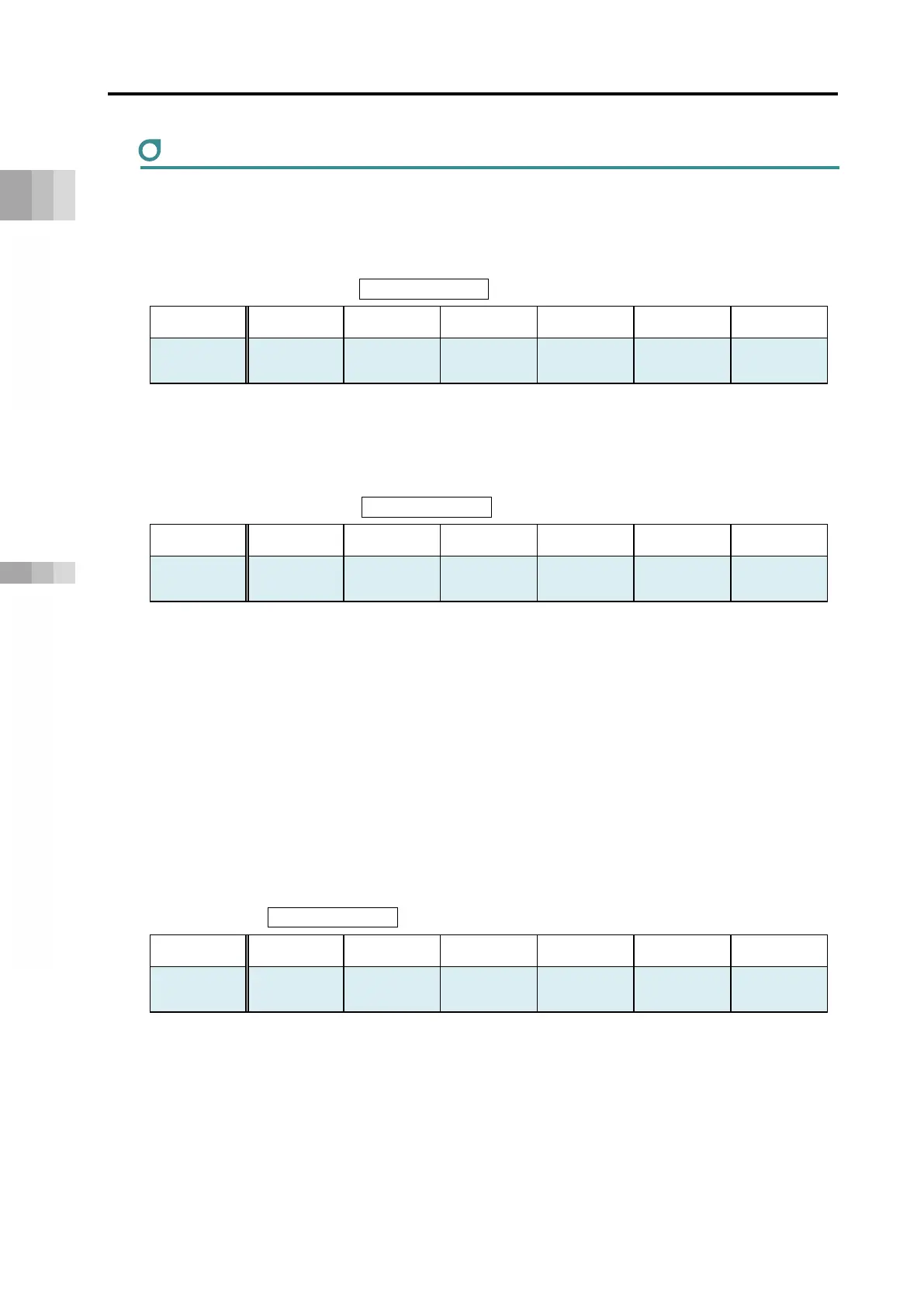
[1] Controller ready (CRDY) PLC input signal
Operation mode
Direct numerical control
Simple direct
Positioner 1 Positioner 2 Positioner 3 Positioner 5
○: Y
: N
○ ○ ○ ○ × ○
Regardless of the alarm status, servo status and the like, when the power is turned ON, driver
unit initialization normally completes, and control is enabled, it turns ON.
It will turn ON even during alarm status if the driver unit is enabled.
[2] Emergency stop (EMGS) PLC input signal
Operation mode
Direct numerical control
Simple direct
Positioner 1 Positioner 2 Positioner 3 Positioner 5
○: Y
×: N
○ ○ ○ ○ ○ ○
This signal turns ON when the condition gets to the motor drive cutoff status.
(1) STOP Signal Input: OFF
(2) MP 24V: OFF
(3) MPI_I or MPI_II Signal: OFF (EMGS: ON only on axis with motor drive source cut off)
(4) 200V Power Supply input:OFF
It turns OFF once the motor drive cutoff status gets cancelled.
Also, the SYS of the driver unit LED lights up in red.
On the host device such as a PLC, apply appropriate safety measures such as interlocking
using this signal.
It is not an output signal caused by the driver unit alarm.
[3] Alarm (ALM) PLC input signal
Operation mode
Direct numerical control
Simple direct
Positioner 1 Positioner 2 Positioner 3 Positioner 5
○: Y
: N
○ ○ ○ ○ ○ ○
It is a signal that turns OFF when it is normal and turns ON when an alarm of operation cancel
level or higher is generated.
This signal turns OFF when the reset signal RES is turned ON while the operation cancel level
alarm is generated. (For a cold start level alarm, the power must be turned on again.)
Also, the SYS of the driver unit LED lights up in red.
For details on alarms, refer to "Maintenance Section Chapter 2, 2.4 Simple Absolute Unit Alarm
Causes and Countermeasures".

 Loading...


