4.4 Part Names/Functions and External Dimensions
A4-25
ME0384-4A
Chapter 4 24V Driver Unit EC Connection Unit
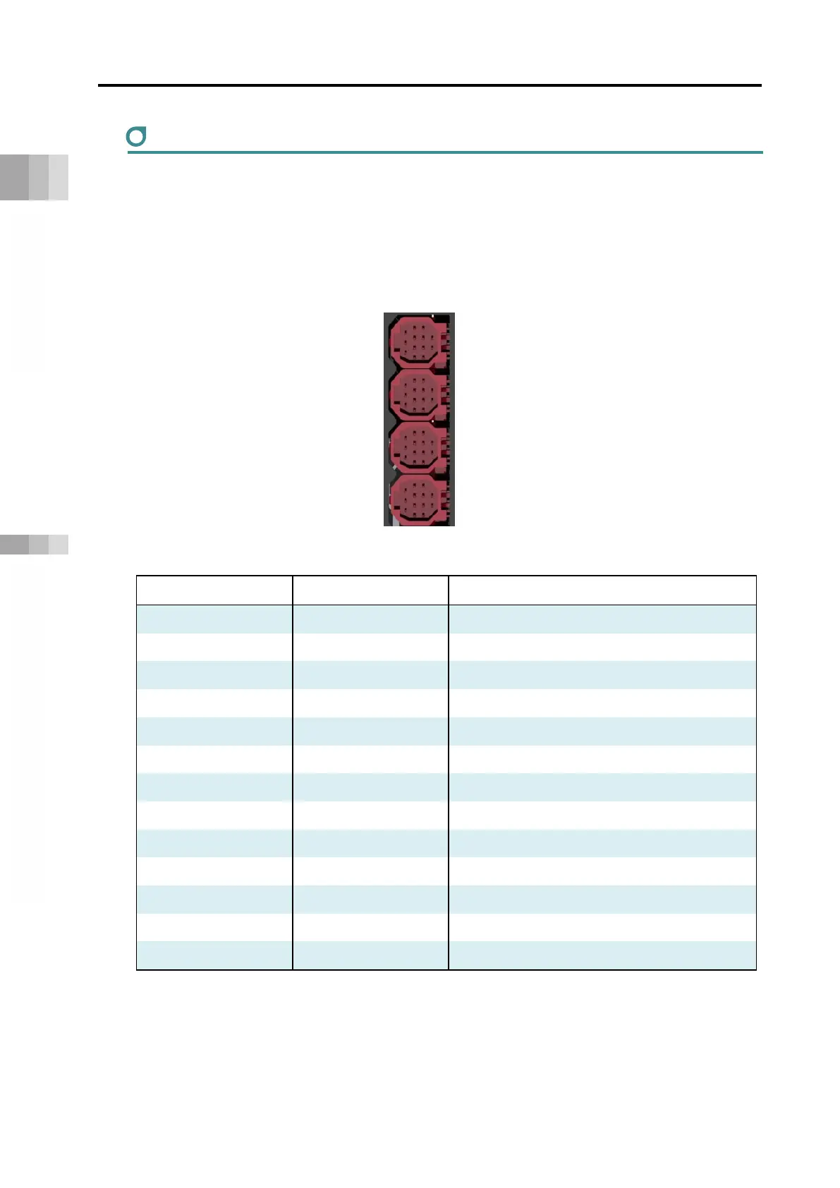
Connectors for EC Connection
They are connectors to connect ELECYLIDER. It comes the connectors for 1st, 2nd, 3rd and 4th
axes from the top.
The axis numbers should be automatically assigned to the numbers after the driver units and
SCON extension unit. Axis numbers for four axes should be assigned to the EC connection unit
even if ELECYLINDER is not connected to all of four. An axis number that an axis is not connected
should not be pulled one number forward.
[RCON-EC]
Pin No. Signal name Description
1
24V (MP) Motor power +24V
2 GND 0V
3 IN0 Input 0
4 IN1 Input 1
5
IN2 Input 2
6
SD+ Communication Line +
7
OUT0 Output 0
8 OUT1 Output 1
9 OUT2 Output 2
10 SD- Communication Line -
11
BKRLS Brake Release
12
24V (CP) Control Power Supply +24V
13
FG Frame Grounding

 Loading...


