2.5 Connection Diagrams
A2-50
ME0384-4A
Chapter 2 System Configuration and Specifications
Field network wiring
For details of the connection method, follow the instruction manuals of the master unit of each
field network and the PLC configured.
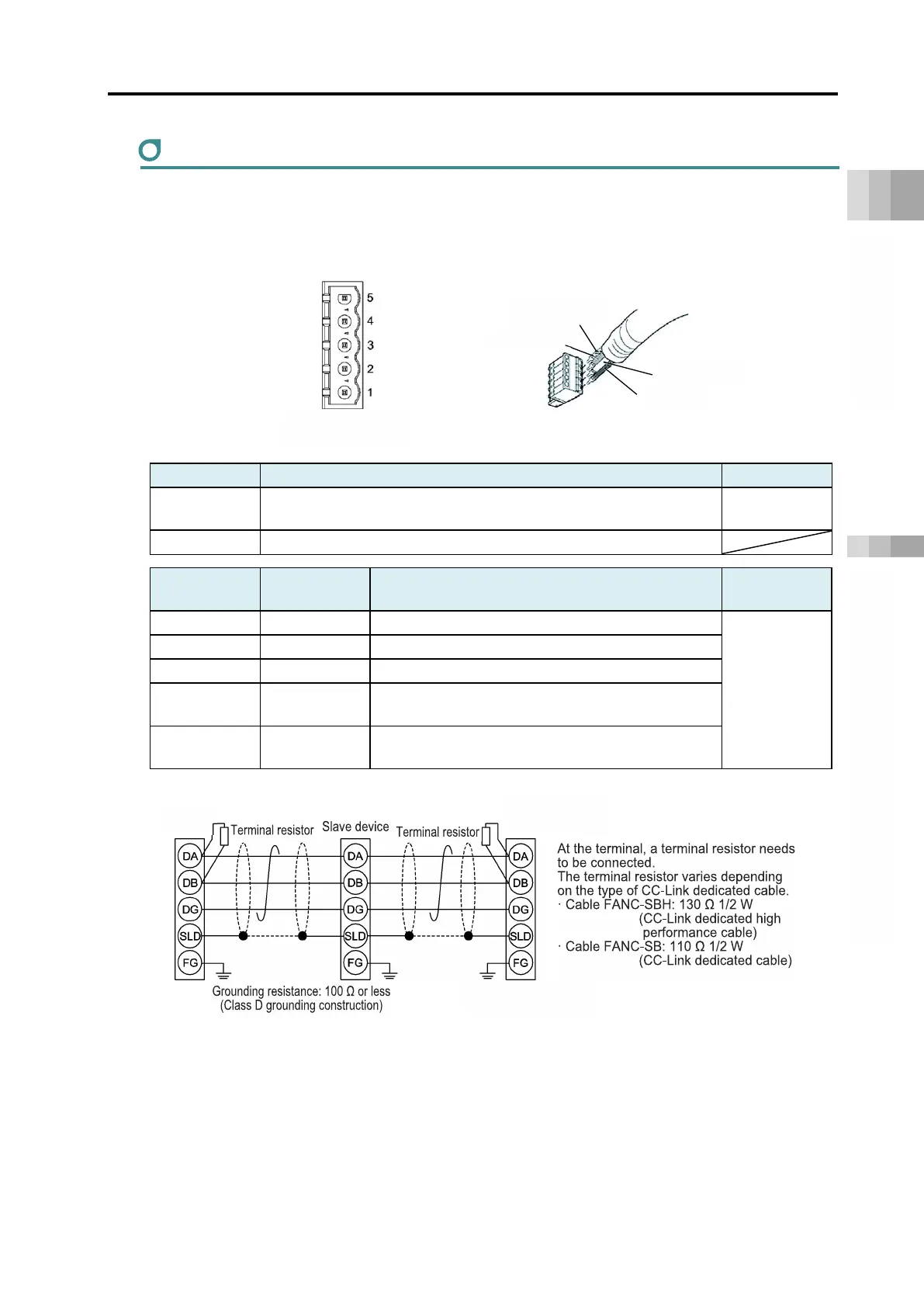
[CC-Link]
Cable side MSTB2.5/5-STF-5.08 AU (Phoenix Contact)
MSTB2.5/5-GF-5.08 AU (Phoenix Contact)
Pin No.
Signal name
(color scheme)
Description
CC-Link
dedicated
cable
4 SLD
Connects the shield of shielded cables
(5-pin FG and control power connector 1-pin FG connected internally)
5 FG
Frame ground
(4-pin SLD and control power connector 1-pin FG connected internally)
Controller side
Connector top view
-CC-Link
SLD and FG are
internally connected.