3.7 Address Configuration
A3-65
ME0384-4A
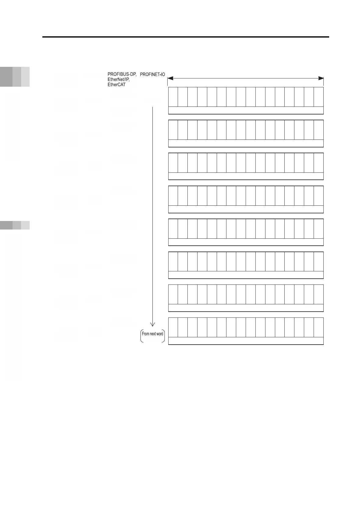
PLC input = Axis status signal
Address
*1
*1 m is the head register address of each axis. n is the head relative address of each axis.
p is the head module address of each axis.
CC-Link, CC-Link IE Field, and DeviceNet have word addresses, PROFIBUS-DP, EtherNet/IP,
and EtherCAT use byte addresses, and PROFINET-IO uses 4-word module addresses.
*2 The present current value should be the command current value for the stepper motor and be the
feedback current value for the AC servomotor (including AC servomotor connected to SCON-CB).
Note: When direct numerical control mode is used with field networks other than CC-Link or CC-
Link IE Field, up to 8 axes can be connected.
Present position data (signed integer)
*2
*2
-
-
-
-
-
-
-
-
-
-
-
-
-
-
-
-
-
-
-
-
SV
ALM
b15
b14
b13
b12
b11
b10
b9 b8 b7 b6 b5 b4 b3 b2 b1 b0
Present position data (signed integer)
512
256
128
64
32
16
8
4
2
1
-
RWr
RWr
RWr
RWr
RWr
RWr
RWr
RWr

 Loading...


