3.7 Address Configuration
A3-66
ME0384-4A
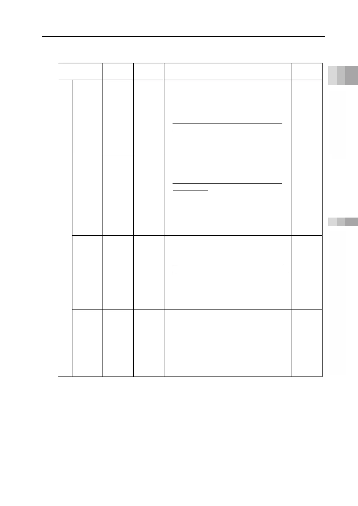
[I/O Signal List]
Direct numerical control mode
(ON = corresponding bit is "1", OFF = corresponding bit is "0")
Signal type Bit
Content Details
PLC output
Position
specified
data
32-bit
data
-
32-bit signed integer (unit: 0.01 mm; 0.001°
for DD motor).
Ex) For +25.40 mm, specify as 2540.
● The maximum set value is +9,999.99 mm =
999999.
● Set the position data within the software
stroke range.
● For negative numbers, specify with 2’s
complement when input is made in a
Page
A3-121
Positioning
width
32-bit
data
-
32-bit integer (unit: 0.01 mm; 0.001° for DD
motor).
Ex) For +25.40 mm, specify as 2540.
● Set the position data within the software
stroke range.
● Specify the direction of push-motion
operation with DIR.
● Note that when the specified positioning
width data is not set, the parameter No.10
"Positioning width initial value" will not be
Page
A3-121
Speed
16-bit
data
-
16-bit integer (unit: 1.0 mm/s or 0.1 mm/s).
Ex) For 200mm/s, specify as 200 when unit =
1.0mm/s
● If the speed is not set or set as "0", it will
remain stopped. Alarm will not be triggered.
If the speed is changed by setting to "0"
during travel, it will decelerate and stop.
● The unit can be switched with the gateway
parameter configuration tool. (It is set to
Page
A3-121
Acceleration/
deceleration
16-bit
data
-
16-bit integer (unit: 0.01G).
Ex) When setting at 0.20 G, specify as 20.
●
Note that when the
acceleration/deceleration is not set, the
parameter No.9 "Acceleration/deceleration
initial value" will not be applied.
● The acceleration and deceleration cannot
be individually set. They will be set
together as acceleration/deceleration.
Page
A3-121

 Loading...


