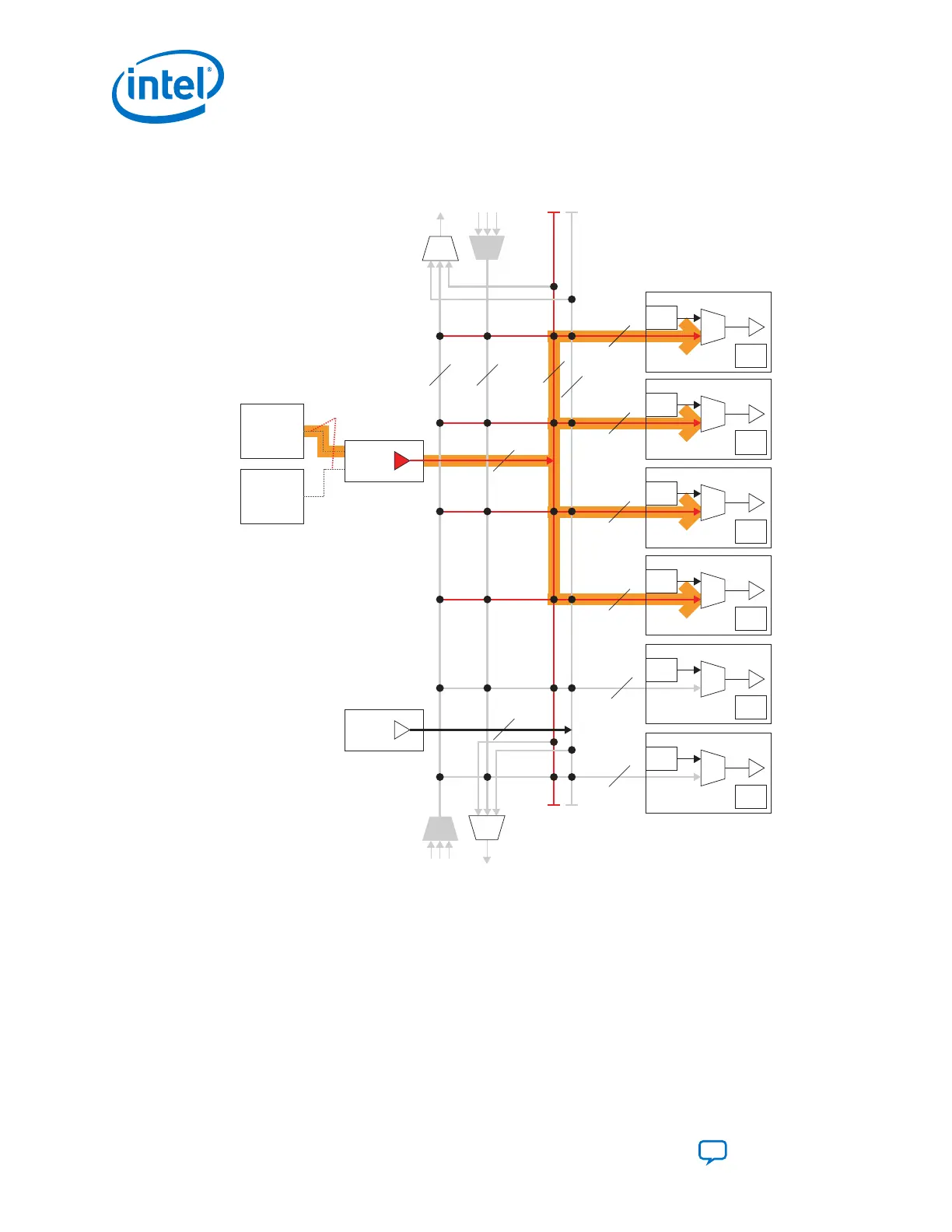
Figure 65. Use ATX PLL or fPLL for Gen1/Gen2 x4 Mode
CDR
CGB
Ch 4
CDR
CGB
Ch 3
CDR
CGB
Ch 2
CDR
CGB
Ch 1
CDR
CGB
Ch 0
CDR
CGB
Ch 5
X6
Network
6
6
6 6
6
6Master
CGB1
Master
CGB0
XN
Network
ATX PLL1
fPLL1
Connections Done
via X1 Network
Notes:
1. The figure shown is just one possible combination for the PCIe Gen1/Gen2 x4 mode.
2. The x6 and xN clock networks are used for channel bonding applications.
3. Each master CGB drives one set of x6 clock lines.
4. Gen1/Gen2 x4 modes use either ATX PLL or fPLL only.
6.
5. Connect pll_pcie_clk from either ATX PLL or fPLL to the pipe_hclk_in port on Native PHY.
In this case the Master PCS channel is logical channel 3 (physical channel 4).
Related Information
• Using PLLs and Clock Networks on page 231
For more information about implementing clock configurations and configuring
PLLs.
2. Implementing Protocols in Intel Cyclone 10 GX Transceivers
UG-20070 | 2018.09.24
Intel
®
Cyclone
®
10 GX Transceiver PHY User Guide
Send Feedback
130