Related Information
• Analog Parameter Settings on page 388
• Intel Cyclone 10 GX Register Map
5.1.2.2. Clock Data Recovery (CDR) Unit
The PMA of each channel includes a channel PLL that you can configure as a receiver
clock data recovery (CDR) for the receiver. You can also configure the channel PLL of
channels 1 and 4 as a clock multiplier unit (CMU) PLL for the transmitter in the same
bank.
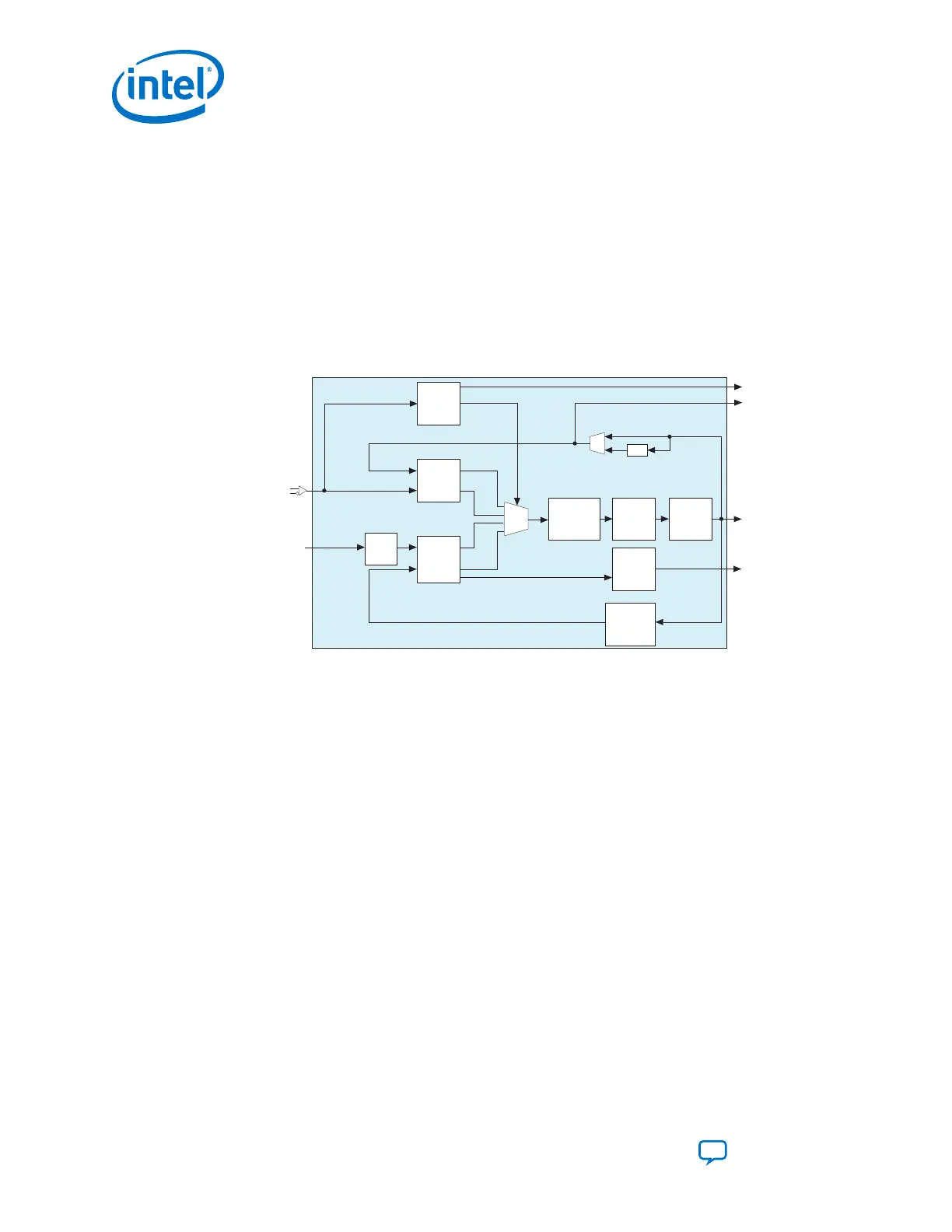
Figure 175. Channel PLL Configured as CDR
Serial Clock
rx_is_lockedtoref
rx_serial_data
refclk
Recovered Clock
LTR/LTD
Controller
Phase
Detector
(PD)
Down
Up
Up
Down
Charge Pump
&
Loop Filter
Voltage
Controlled
Oscillator
(VCO)
Lock
Detect
Phase
Frequency
Detector
(PFD)
/2
Channel PLL
M
Divider
(1)
Note:
1. The Quartus® Prime Pro Edition software automatically chooses the optimal values.
rx_is_lockedtodata
N
Divider
(1)
L
Divider
(1)
5.1.2.2.1. Lock-to-Reference Mode
In LTR mode, the phase frequency detector (PFD) in the CDR tracks the receiver input
reference clock. The PFD controls the charge pump that tunes the VCO in the CDR.
The rx_is_lockedtoref status signal is asserted active high to indicate that the
CDR has locked to the phase and frequency of the receiver input reference clock.
Note: The phase detector (PD) is inactive in LTR mode.
5.1.2.2.2. Lock-to-Data Mode
During normal operation, the CDR must be in LTD mode to recover the clock from the
incoming serial data. In LTD mode, the PD in the CDR tracks the incoming serial data
at the receiver input. Depending on the phase difference between the incoming data
and the CDR output clock, the PD controls the CDR charge pump that tunes the VCO.
Note:
The PFD is inactive in LTD mode. The rx_is_lockedtoref status signal toggles
randomly and is not significant in LTD mode.
After switching to LTD mode, the rx_is_lockedtodata status signal is asserted.
The actual lock time depends on the transition density of the incoming data and the
parts per million (ppm) difference between the receiver input reference clock and the
upstream transmitter reference clock. The rx_is_lockedtodata signal toggles until
5. Cyclone 10 GX Transceiver PHY Architecture
UG-20070 | 2018.09.24
Intel
®
Cyclone
®
10 GX Transceiver PHY User Guide
Send Feedback
280