To enable serial loopback mode:
1. Perform the necessary steps from steps 1 to 7 in Steps to Perform Dynamic
Reconfiguration.
2. Perform a read-modify-write to address 0x2E1 to set bit 0 to 1’b1
3. Perform the necessary steps from steps 9 to 12 in Steps to Perform Dynamic
Reconfiguration.
To disable serial loopback mode:
1. Perform the necessary steps from steps 1 to 7 in Steps to Perform Dynamic
Reconfiguration.
2. Perform a read-modify-write to address 0x2E1 to set bit 0 to 1’b0
3. Perform the necessary steps from steps 9 to 12 in Steps to Perform Dynamic
Reconfiguration.
You can also enable the serial loopback mode by turning on Enable rx_seriallpbken
port in the Native PHY IP Parameter Editor and driving the port to 1’b1.
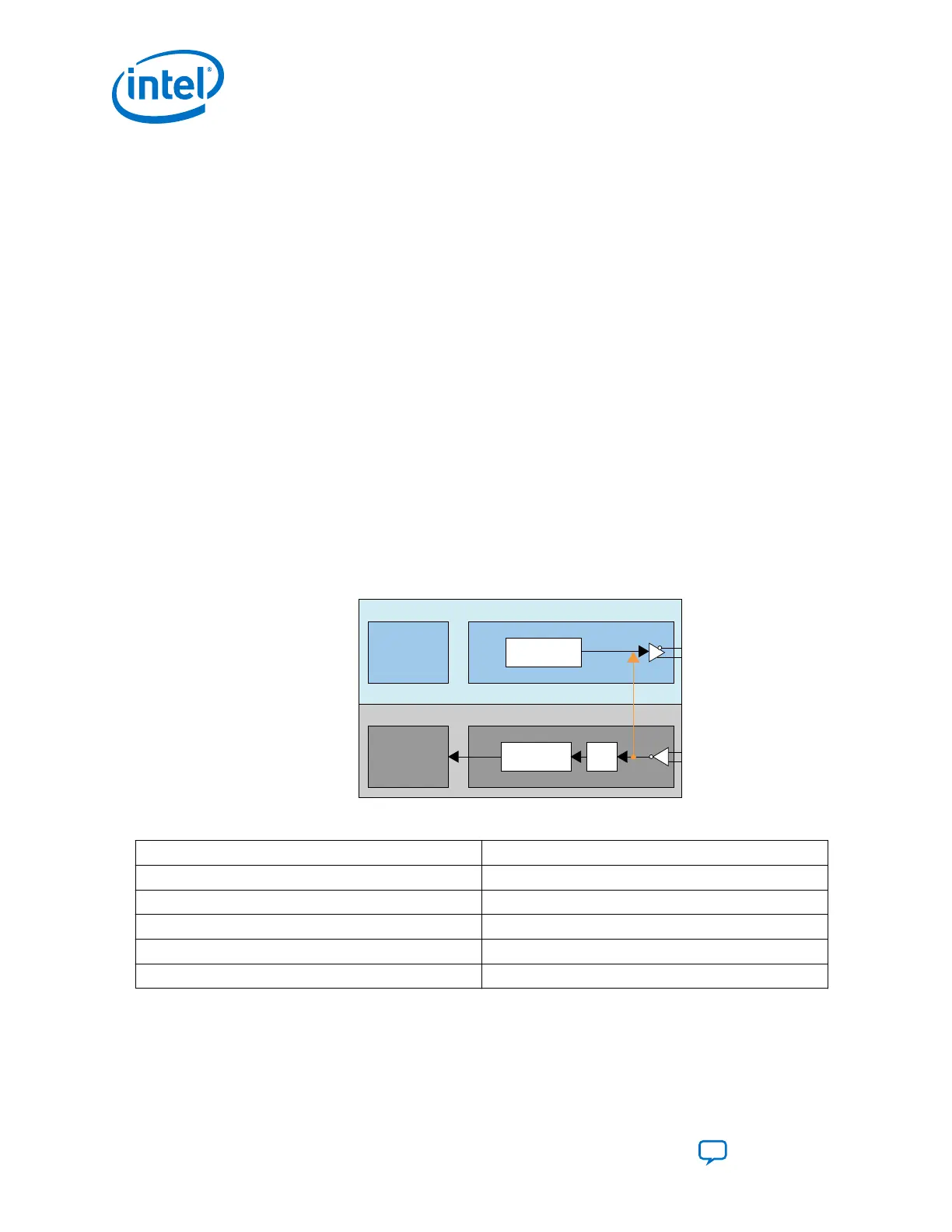
Reverse Serial Loopback Mode (Pre-CDR)
In the pre-CDR mode, data received through the RX input buffer is looped back to the
TX output buffer. You can enable the reverse serial loopback mode by performing
read-modify-write to the following registers.
Figure 215. Reverse Serial Loopback Mode (Pre-CDR)
PCS PMA
Serializer
PCS PMA
Deserializer
Transmitter
Receiver
CDR
Pre-CDR Reverse
Serial Loopback
Table 188. Bit Values to Be Set
Address Bit Values
0x137[7] 1’b1
0x13C[7] 1’b0
0x132[5:4] 2’b00
0x142[4] 1’b1
0x11D[0] 1’b1
Note: No specific order to access these registers.
6. Reconfiguration Interface and Dynamic Reconfiguration
UG-20070 | 2018.09.24
Intel
®
Cyclone
®
10 GX Transceiver PHY User Guide
Send Feedback
344