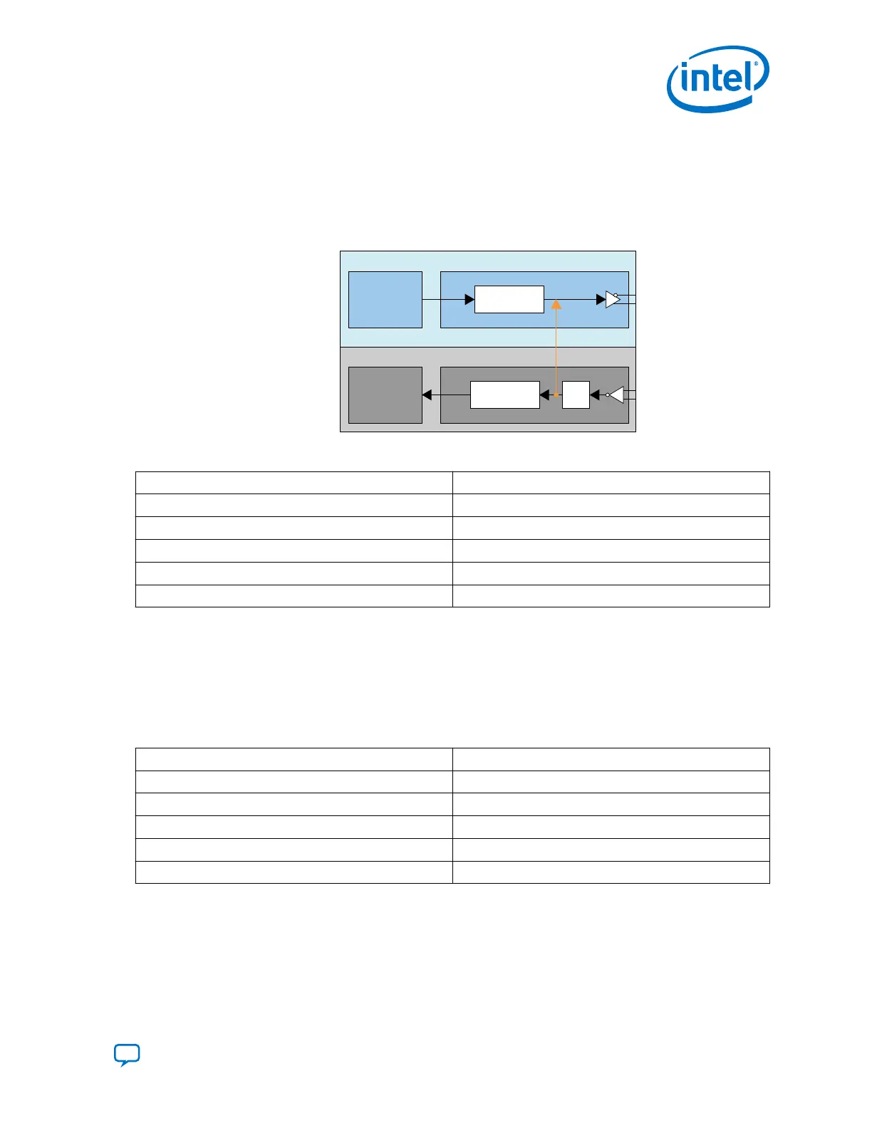
Reverse Serial Loopback Mode (Post-CDR)
In the post-CDR mode, received data passes through the RX CDR and then loops back
to the TX output buffer. Perform read-modify-write to the following registers to enable
this mode.
Figure 216. Reverse Serial Loopback Mode (Post-CDR)
PCS PMA
Serializer
PCS PMA
Transmitter
Receiver
Deserializer CDR
Post-CDR Reverse
Serial Loopback
Table 189. Bit Values to Be Set
Address Bit Values
0x137[7] 1’b0
0x13C[7] 1’b1
0x132[5:4] 2’b01
0x142[4] 1’b0
0x11D[0] 1’b0
Note: No specific order to access these registers.
Disabling Reverse Serial Loopback Mode (Pre-CDR and Post-CDR)
To disable reverse-serial loopback mode, set the address bits to the following values,
by performing read-modify-write.
Table 190. Bit Values to Be Set
Address Bit Values
0x137[7] 1’b0
0x13C[7] 1’b0
0x132[5:4] 2’b00
0x142[4] 1’b0
0x11D[0] 1’b0
Note: No specific order to access these registers.
Related Information
Steps to Perform Dynamic Reconfiguration on page 328
6. Reconfiguration Interface and Dynamic Reconfiguration
UG-20070 | 2018.09.24
Send Feedback
Intel
®
Cyclone
®
10 GX Transceiver PHY User Guide
345