Actions Yes No
Step 1
Turn the printer off.
Remove the rear shield. See
“Rear cover removal” on page 307.
Remove the operator panel. See
“Operator panel removal (for CX310 and
CX410 models only)” on page 276.
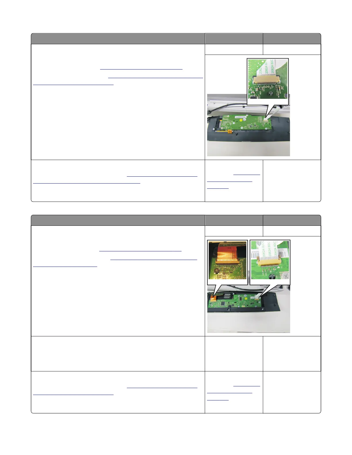
Is the operator panel cable properly installed at JLCD1 on the controller
board and the operator panel assembly?
Note: JLCD1 is the ribbon cable connector on the right side facing the
controller board.
Go to step 2. Reinstall the cable.
Step 2
Replace the UICC card with display. See
“Operator panel removal (for
CX310 and CX410 models only)” on page 276.
Does the operator panel display all diamonds?
Replace the controller
board. See
“Controller
board removal” on
page 309.
Problem resolved.
For CX510 models:
Actions Yes No
Step 1
Turn the printer off.
Remove the rear cover. See
“Rear cover removal” on page 307.
Remove the operator panel. See
“Operator panel removal (for CX510
models only)” on page 283.
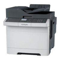
Is the operator panel cable properly installed at JLCD1 on the controller
board and the operator panel assembly?
Note: JLCD1 is the ribbon cable connector on the right side facing the
controller board.
Go to step 2. Reinstall the cable.
Step 2
Check UICC card to display cable.
Is the display cable installed at the UICC card correctly?
Go to step 3. Reinstall the cable.
Step 3
Replace the UICC card with display. See
“Operator panel removal (for
CX510 models only)” on page 283.
Does the operator panel display all diamonds?
Replace the controller
board. See
“Controller
board removal” on
page 309.
Problem resolved.
7527
Diagnostic information
132