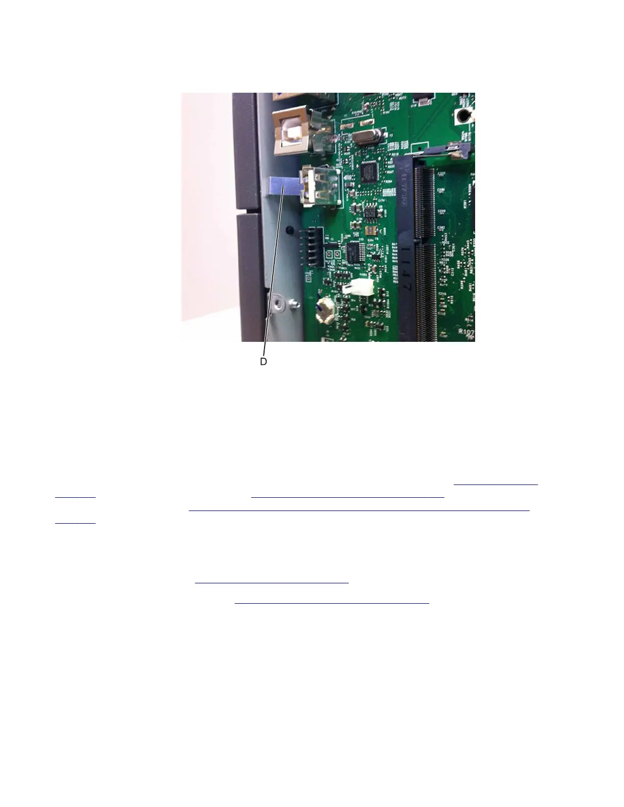
• Make sure the ground contact on the JUSB1 connector (D) comes into contact with the controller board cage
after installing the controller board.
Warning—Potential Damage: When replacing the controller board, verify that the cable from the high-voltage
power supply is seated properly. The cable may have been loosened from the HVPS. Print a few pages to verify
the installation. If the pages are blank, then confirm that the high-voltage power supply cable is properly seated.
The connector may have been loosened at the HVPS. A blank page that should have toner on it could be an
indication that toner is applied to the ITU belt but is not transferred. Therefore the toner goes into the ITU
cleaner which cannot process massive amounts of toner. It is important to prevent extensive blank pages from
being processed if they should have toner on them.
Installation note: After replacing the controller board, perform the Motor Detect test (see
“Motor Detect” on
page 197), Scanner manual registration (see “Scanner manual registration” on page 222), and the printer
configuration restoration (see
“Restoring the printer configuration after replacing the controller board” on
page 229).
System fan removal
1 Remove the rear cover. See “Rear cover removal” on page 307.
2 Remove the left cover assembly. See “Left cover assembly removal” on page 246.
3 Remove the back AIO cable cover.
4 Unplug the top of the system fan from the controller board.
7527
Repair information
311