• Operator panel assembly
• Controller board
Note: The UICC card is part of the operator panel.
Note: The following parts (FRUs) can be accessed from this section:
• Operator panel (one for each CX310 and CX410)
• Display and PCBA (CX310)
• Display (CX410)
• UICC PCBA (CX410)
• User interface support bracket (common to CX310 and CX410)
• Front operator panel cover (common to CX310 and CX410)
• Upper front (operator) cover (common to CX310 and CX410)
• Speaker (CX410)
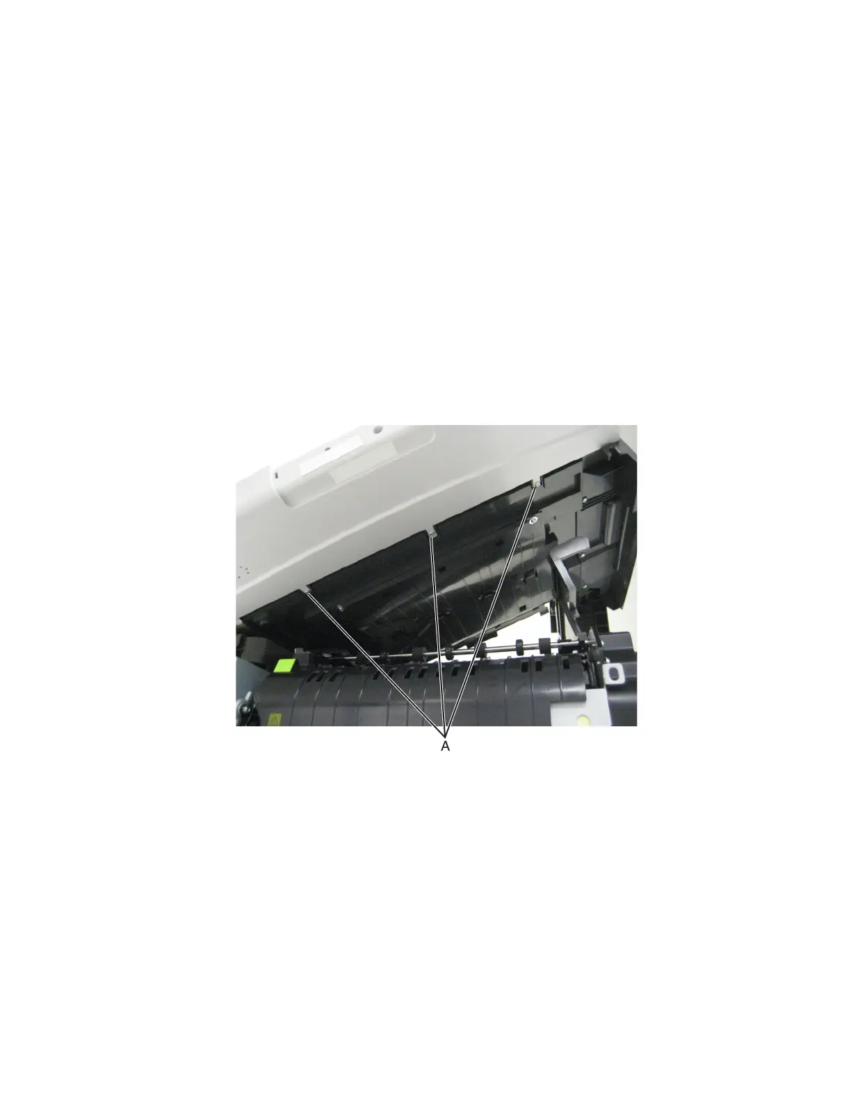
1 Lift the flatbed scanner assembly on the right side.
2 Remove the three screws (A) from beneath the operator panel.
7527
Repair information
277