214683 136 Revision A
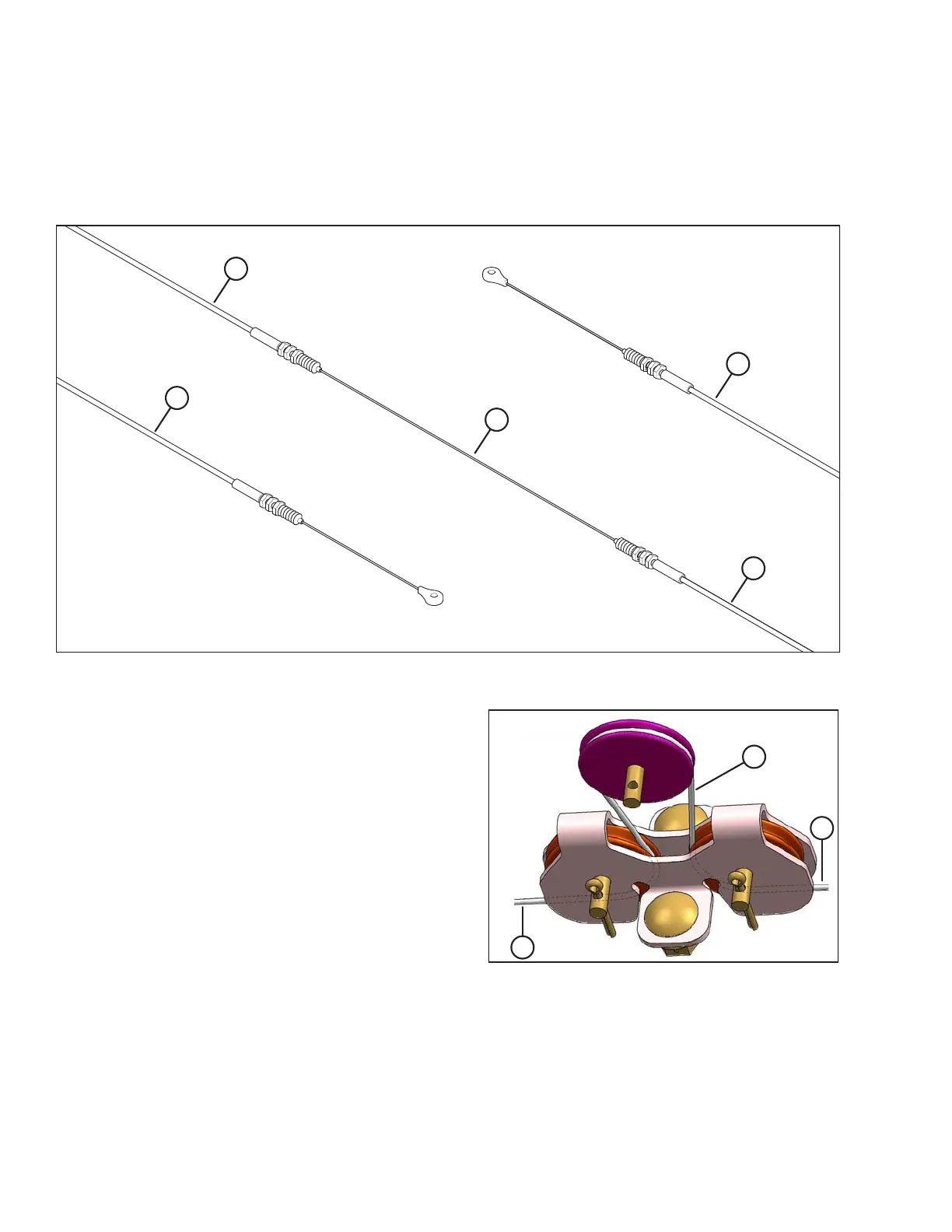
6. Examine the new float indicator cable (MD #187658). You will see that it is divided into sections. The longer
covered section (A) will be installed on the left side of the float module, the middle uncovered section (B) will be
installed in the float indicator box, and the shorter covered section (C) will be installed on the right side of the
float module. Installation instructions are provided in the following steps.
Figure 3.176: Float Indicator Cable
A - Longer Covered Cable Section
1788–1800 mm (70-3/8–70-7.8 in.)
B - Uncovered Middle Cable Section C - Shorter Covered Cable Section
1352–1364 mm (53-1/4–53-11/16 in.)
Figure 3.177: Cable Routing around Pulleys
7. With the longer end of the new float indicator cable on
the left, loop the middle section of the cable (the section
in between the innermost boot seals and jam nuts) (A)
around the three pulleys in the float indicator box as
shown at right.
OPERATION