214683 137 Revision A
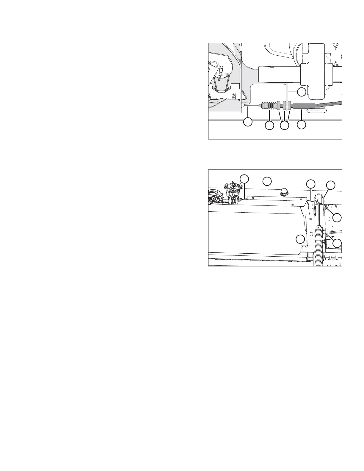
Figure 3.178: Float Indicator Cable Secured to
Left Side of the Float Indicator Bottom Support
– Right Side is Opposite
8. Secure the left side of the new float indicator cable (A)
to the left side of the float indicator bottom support as
follows:
a. On float indicator cable (A), jam nuts and boot
seals are positioned in four locations. Select the
second location from the left.
b. Remove boot seal (B), and slide cable (A) through
the slot on the left side of the float indicator bottom
support (C).
c. Insert the threaded end of cable housing (D) into
the hole in support (C), and then thread boot
seal (B) onto the housing.
d. Tighten jam nuts (E).
Figure 3.179: Cable Routing on Left Side of
Float Module
9. Route the left end of the new float indicator cable (A)
through hose holder (B), behind gussets (C) at the top
of the inboard float spring, through hole (D) into the float
module hydraulic/electrical enclosure, and then back
through hole (E) in the bottom of the float module
hydraulic/electrical enclosure to the front side of the
float module.
OPERATION