214683 302 Revision A
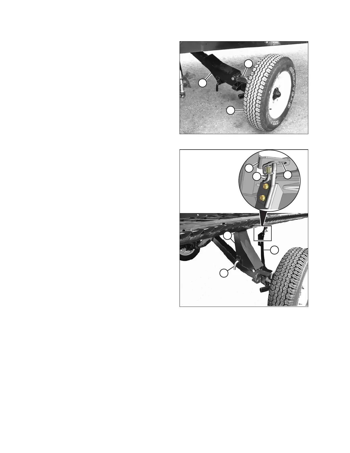
Figure 3.536: Right Rear Wheel
10. Lock the wheel (A) with pin (B). Move the right axle (C)
to the front of the header.
Figure 3.537: Right Rear Wheel Position
11. Remove the pin (A), raise support (B) to the position
shown, and reinsert pin.
IMPORTANT:
Ensure the pin (A) engages the tube on the axle.
12. Swing the brace (C) into the position shown and insert
the brace into the slot (D) behind the cutterbar. Position
the brace so that pin (E) engages the hole in the
bracket (F). The right wheel is now in transport position.
13. Disengage the header cylinder lift stops.
14. Detach the header’s hydraulic and electrical
connections from the combine. Refer to 4 Header
Attachment/Detachment, page 307.
15. Start the combine and lower the header to the ground.
OPERATION