214683 334 Revision A
Figure 4.53: Hydraulic Connection
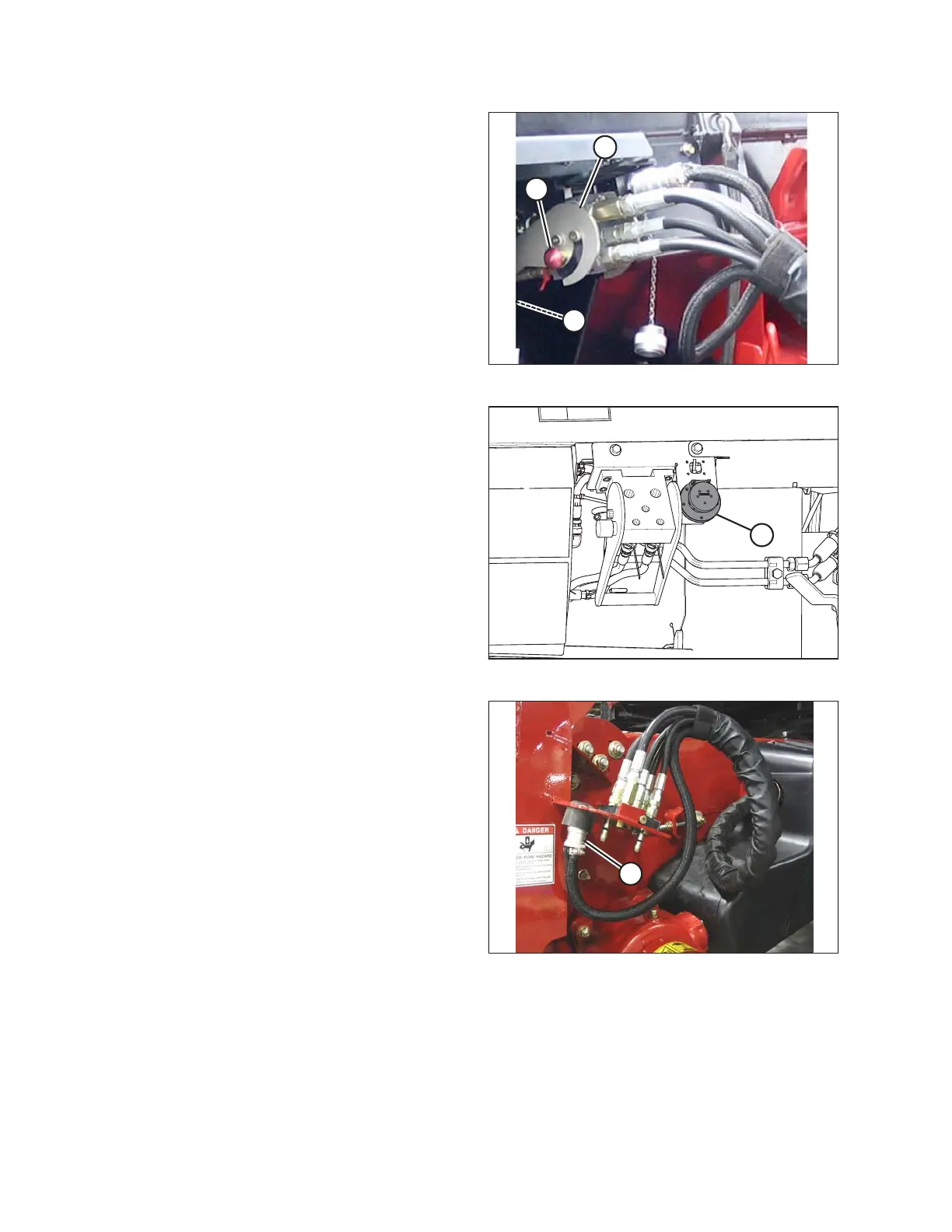
12. Position the coupler onto the coupler receptacle (A) and
push the handle (B) (not shown) to engage the
multicoupler pins into the receptacle.
13. Push the handle (B) to the closed position until the lock
button (C) snaps out.
Figure 4.54: Electrical Receptacle
14. Remove the cover from the electrical receptacle (A).
Ensure the receptacle is clean and has no signs of
damage.
Figure 4.55: Combine Connectors
15. Remove the electrical connector (A) from the storage
cup on the combine and route it to the float module
receptacle.
HEADER ATTACHMENT/DETACHMENT