214683 357 Revision A
Figure 4.107: Receptacle Cover
9. Place the float module receptacle cover (A) onto the
combine receptacle.
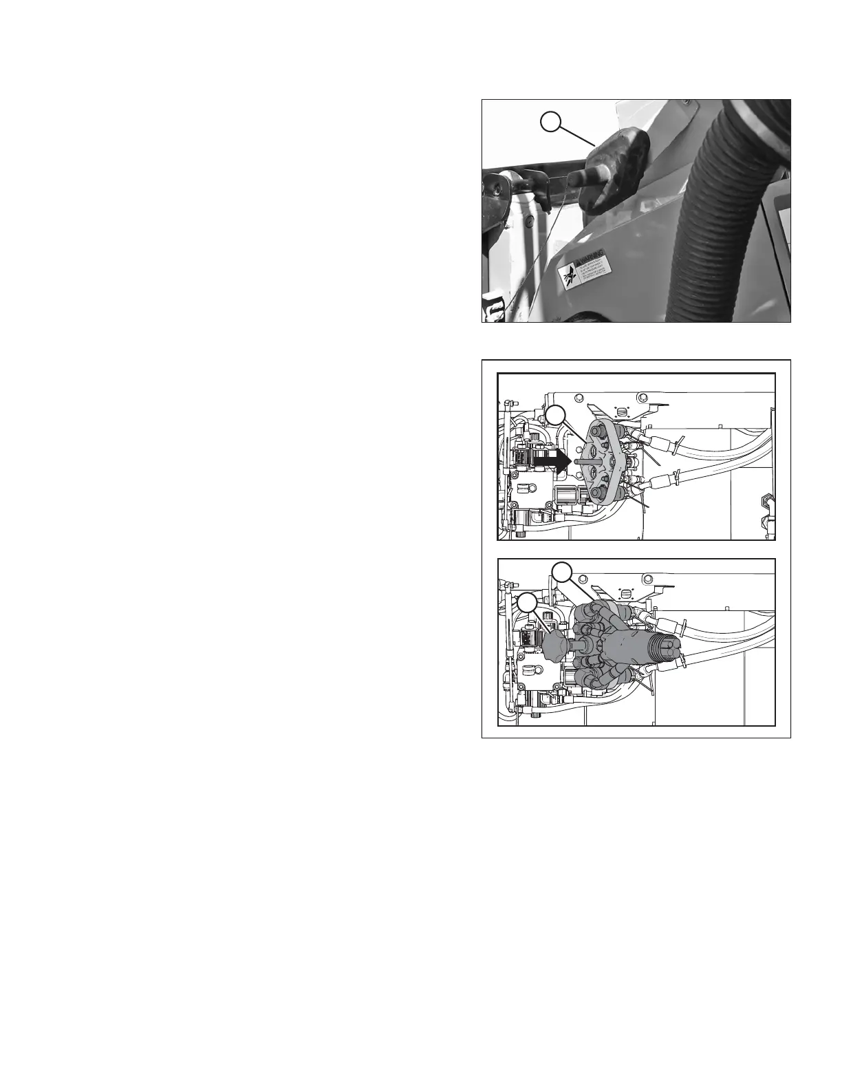
Figure 4.108: Coupler
10. Clean the mating surface of the coupler (A) and position
onto the float module receptacle (B).
11. Turn the knob (C) to secure the coupler to the
receptacle.
HEADER ATTACHMENT/DETACHMENT