214683 365 Revision A
Figure 4.124: Combine Coupler
11. Remove the hydraulic quick coupler (A) from the
storage plate on the combine, and clean the mating
surface of the coupler.
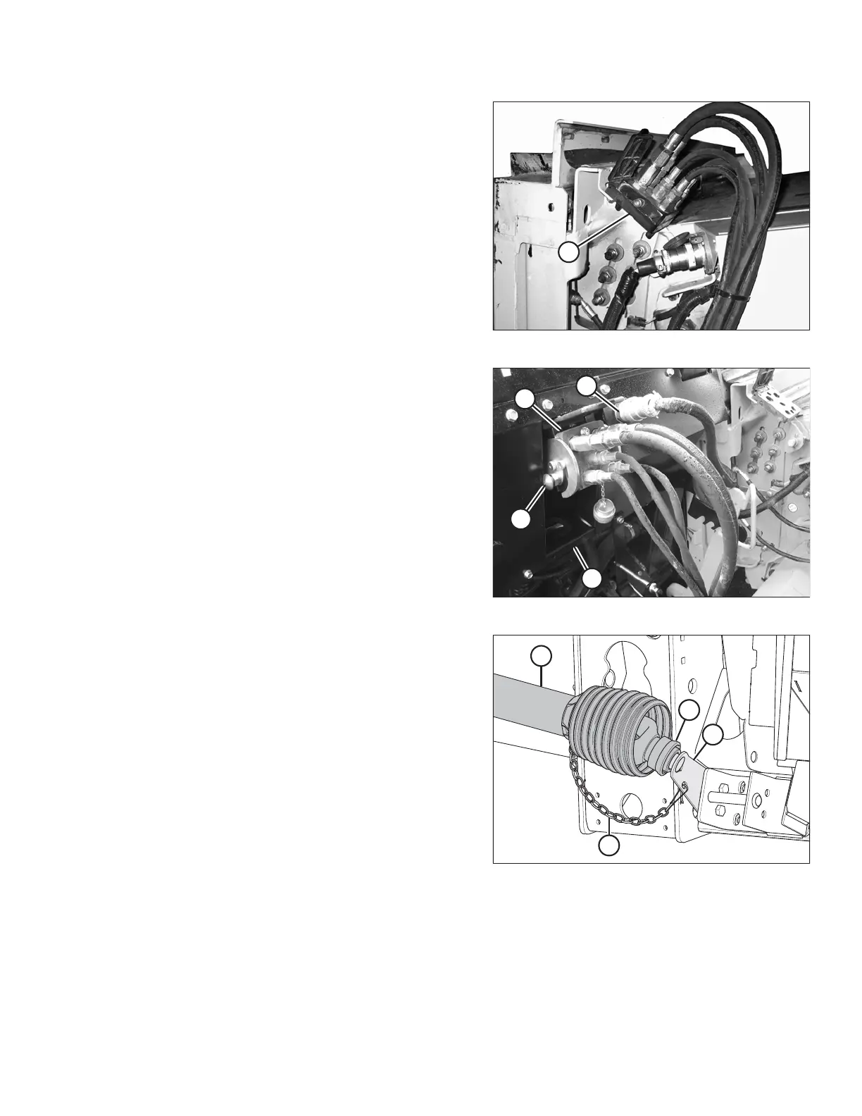
Figure 4.125: Connections
12. Position the coupler (A) onto the float module
receptacle, and push the handle (B) to engage the pins
into the receptacle.
13. Push the handle (B) to closed position until the lock
button (C) snaps out.
14. Remove the cover on the float module electrical
receptacle.
15. Remove the connector (D) from the combine.
16. Align the lugs on the connector (D) with the slots in the
float module receptacle, and push the connector onto
the receptacle. Turn the collar on the connector to lock
it in place.
Figure 4.126: Driveline in Storage Position
17. Detach safety chain (C) from support bracket (B).
18. Pull collar (D) back to release driveline (A) from support
bracket. Remove the driveline from support bracket.
HEADER ATTACHMENT/DETACHMENT