214683 366 Revision A
Figure 4.127: Driveline and Output Shaft
19. Pull back the collar on the end of the driveline, and push
the driveline onto the combine output shaft (A) until the
collar locks.
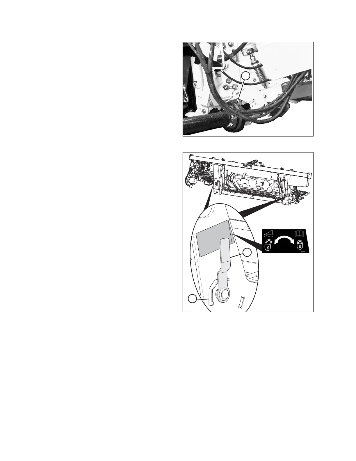
Figure 4.128: Float Lock Handle (Right Side
Shown in Detail, Left Side Opposite)
20. Disengage the float locks by pulling each float lock
handle (A) away from the float module and setting it in
the unlocked position (B).
HEADER ATTACHMENT/DETACHMENT