214683 380 Revision A
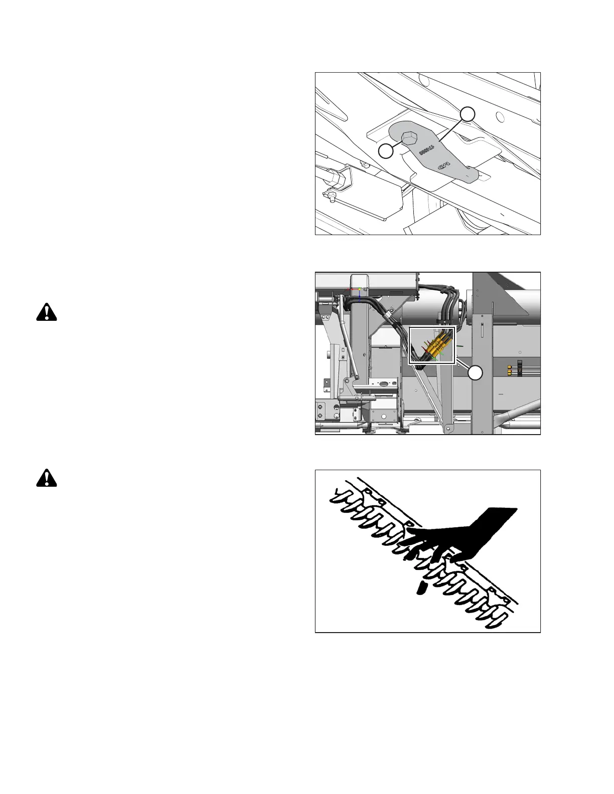
Figure 4.159: FD1 Series Combine Header –
Float Module Underside
13. Replace the pin (B) in the header legs and secure with
ring (A).
14. For FD1 Series Combine Header: Loosen nut and bolt
(A), and reposition hook (B) as shown to engage float
module arm. Tighten bolt and nut (A).
Figure 4.160: Reel Hydraulics
15. Match the colored cable ties and connect the reel
hydraulics (A) at the right end of the float module.
CAUTION
Be sure all bystanders are clear of machine before
starting engine or engaging any header drives.
16. Remove the lift cylinder locks, start the engine, and
lower the header to the ground. Adjust the header angle
to the steepest setting (longest center-link).
17. Raise the reel to its full height.
18. Shut down the engine and remove the key from the
ignition.
19. Engage the reel safety props.
Figure 4.161: Cutterbar Hazard
WARNING
Keep hands clear of the area between guards and knife
at all times.
HEADER ATTACHMENT/DETACHMENT