Pathway Technical Reference Manual
Proprietary 144 of 190
14.3 Parallel Communication
Parallel communication is based on sending 8-bit words from the external application computer
to the Medoc Main Station computer using the parallel ports on both computers.
The following section describes the system requirements for using parallel communication and
setup instructions.
14.3.1 System Requirements
1. Parallel communication requires the external application to be installed on a separate
computer than that of the Medoc Main Station. an additional computer and/or triggering
hardware which will be connected to the Medoc Main Station computer using parallel ports
(D-type 25 pin).
2. Both Medoc Main Station computer and the computer or device used for the external
control must have a physical parallel port (D-type 25 pin). The parallel interface will not
work with a USB-to-Parallel adapter.
3. BIOS settings for the parallel port must be set to EPP mode.
4. Medoc Main Station license must include the External Control Interface. For additional
information please contact your local distributor.
5. Windows 8 operating systems may require additional configurations in order to work with
parallel communication. For further guidance contact Medoc Service.
8-bit triggering voltage needs to be configured according to Medoc Main
Station computer Parallel port configuration. Voltage Configurations may
vary between computers according to manufacturer settings.
Medoc is not responsible for any hardware or operating system issues
related to the functionality of the physical parallel port and cannot support
such issues.
Medoc supplies ONLY the required software for the Parallel Interface.
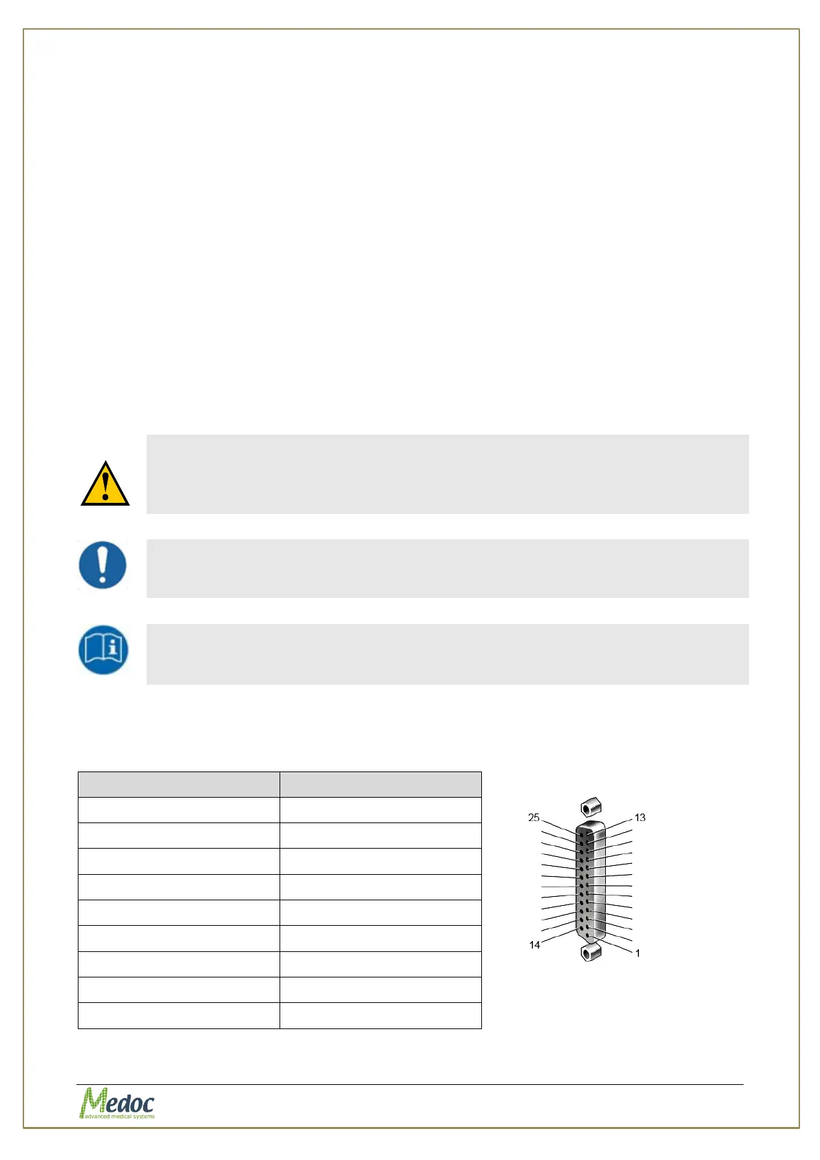
14.3.2 Parallel Connector Configuration
The parallel connector (D-Type 25 pin) should be configured according to the table below:
Figure 100: Female
Connector