Pathway Technical Reference Manual
Proprietary 151 of 190
15.2 Installation – CHEPS MR Filter
1. Complete the setup and installation procedure as described for a regular PATHWAY system,
according to the System Block diagram below.
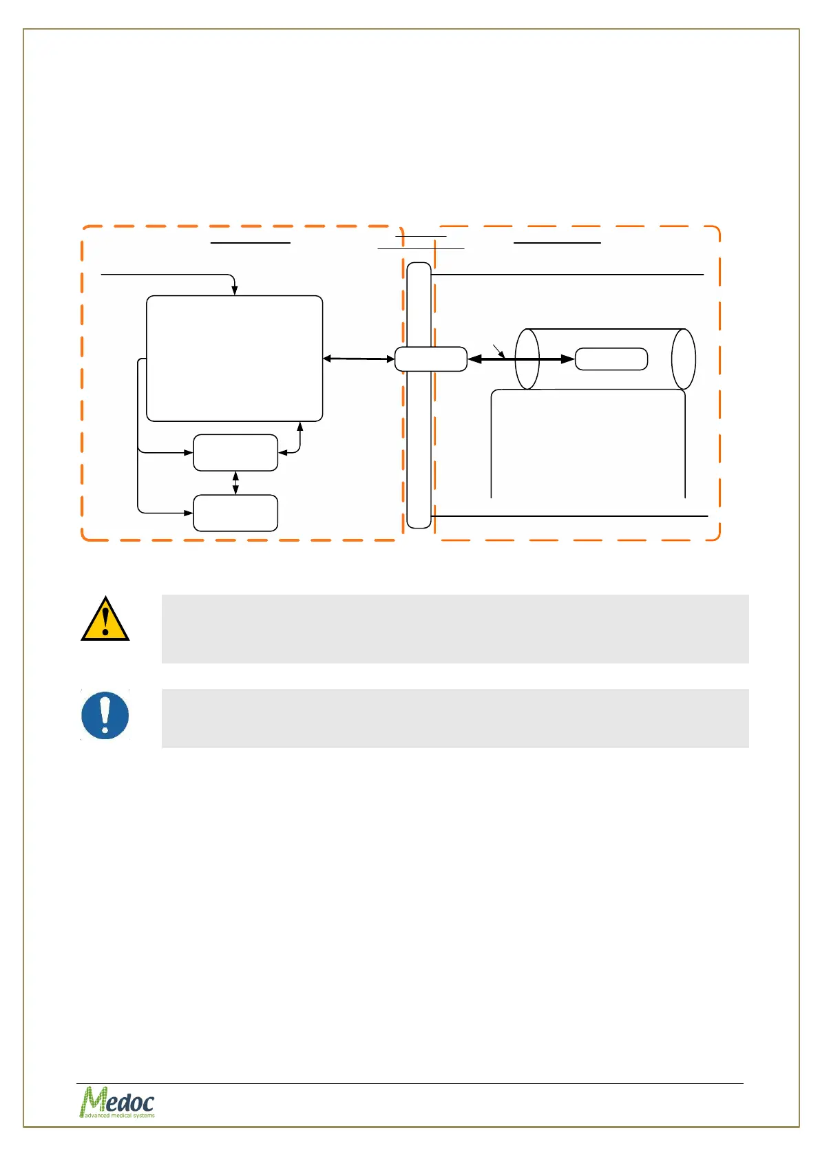
2. Connect the system devices according to the following stages:
2.1. Connect the PATHWAY system so it would be placed in the MRI control room, while the
Thermode itself is placed in the MRI room, as shown in the diagram:
PATHWAY
(Cart)
PC
Filter
MRI Room
Penetration Panel
RS232
Printer
Mains
110/220VAC
Extended
cable
fMRI Thermode
Thermode
Cable 10M
fMRI Scanner
Shielded RoomControl Room
Power
Figure 105: System Block Diagram
The sum of power consumption of laptop and printer
connected to the power inlet of the trolley should be less
than 330 W.
The external laptop and printer should be connected to
power through the system isolation transformer only.
2.2. Make sure your laptop, PATHWAY unit and printer (optional) are all OFF.
2.3. Install the fMRI filter according to the following instructions:
2.3.1. Install the filter on your MRI room penetration panel. You can use 4 screws that
join the two main aluminum parts of the filter.
2.3.2. The fMRI Thermode connectors should be placed inside the fMRI room. All the
other devices' connectors should be placed outside of the fMRI room.