31.5 Remote interface
■■■■■■■■■■■■■■■■■■■■■■
298
■■■■■■■■
917 Coulometer
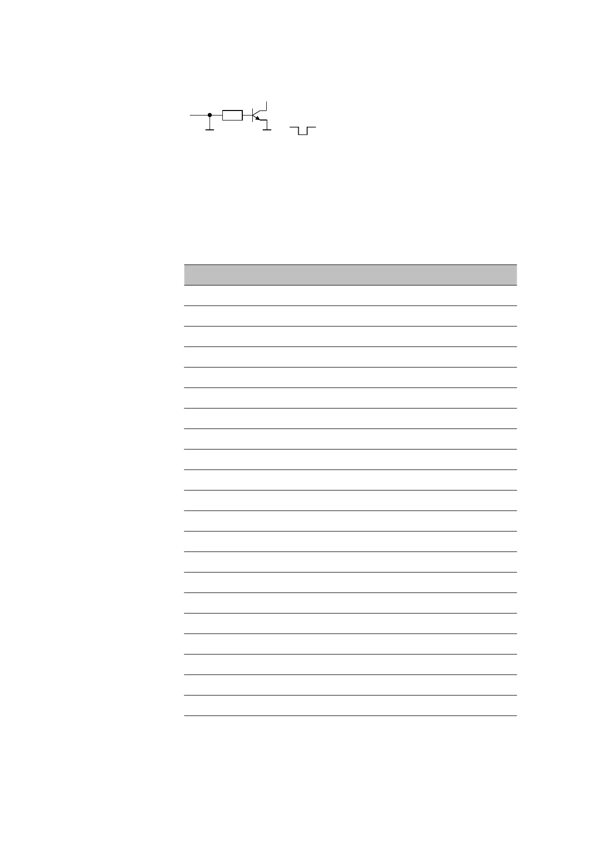
Outputs
Open Collector
t
p
> 200 ms
active = low, inactive = high
I
C
= 20 mA, V
CEO
= 40 V
+5 V: maximum load = 20 mA
The following tables offer information concerning the assignment of the
individual pins and their function.
Table 12
Inputs and outputs of the remote interface
Assignment Pin No. Function
Input 0 21 Start
Input 1 9 Stop
Input 2 22
Input 3 10 Quit
Input 4 23 -
Input 5 11
Input 6 24
Input 7 12
Output 0 5 Ready
Output 1 18 Conditioning OK
Output 2 4 Determination
Output 3 17 EOD
Output 4 3
Output 5 16 Error
Output 6 1
Output 7 2 Warning
Output 8 6
Output 9 7
Output 10 8
Output 11 13
Output 12 19
 Loading...