Implementation
Microsemi Proprietary and Confidential UG0677 User Guide Revision 9.0 99
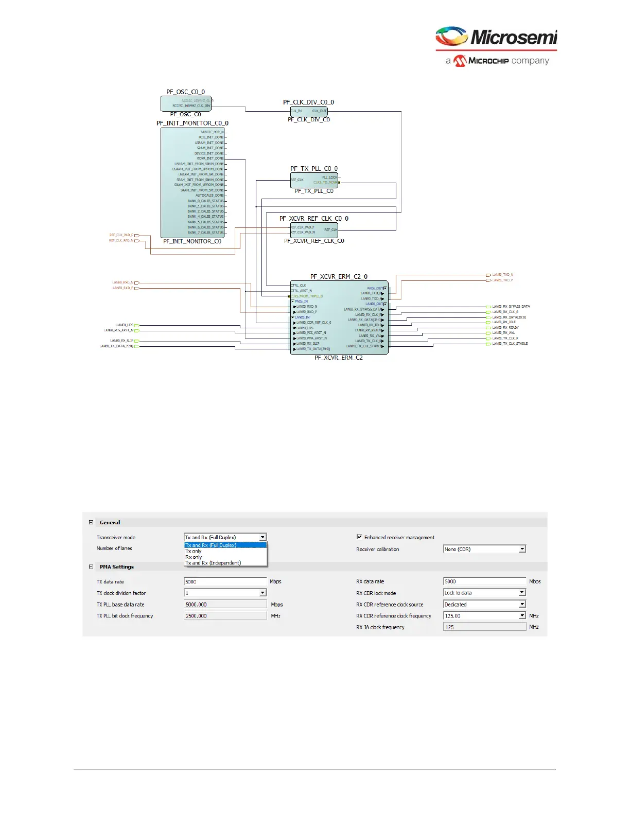
Figure 84 • Completed Transceiver Subsystem with ERM
See the port list tables in Transceiver PCS Interface Modes, page 23 for complete pin descriptions
generated with the Transceiver Configurator.
4.2 Transceiver Modes
The transceiver architecture permits several ways to use the transmit and receive portions of the PMA
and PCS. A TXPLL is not instantiated by the Transceiver configurator. The user must instantiate the
TXPLL. The Transceiver configurator gives the user options to use the Tx and Rx together or
independently or alone. The transceiver modes require the user to input the specific design requirements
to generate the transceiver block. The modes also define the operation of the PMA_ARSTN and
PCS_ARSTN pins and how these pins reset the transceiver functionality.
Figure 85 • Transceiver Modes shown in Transceiver GUI
4.2.1 Full-Duplex Mode
Tx and Rx Duplex support is the most common use of the transceiver and often referred to as full-duplex.
It is defined as the mode where the Rx and Tx portions of the PMA share resources such as clocking and
reset functions. Full duplex uses a common clock for both the Tx and Rx, that is, the base rates and PCS
widths are the same. Both PMA_ARSTN and PCS_ARSTN resets both the Tx and Rx of the PMA and
PCS, respectively.