Functional Description
Microsemi Proprietary and Confidential UG0677 User Guide Revision 9.0 14
example, JESD204B startups with a continuous K28.5 stream, then later shifts to actual 8b10b data. This
is a change in data pattern and may impact calibrated DFE coefficients.
The PolarFire transceiver component is generated by the Libero software to include enhanced receiver
management logic to control the proper calibration of the receiver, see Enhanced Receiver Management,
page 16. The ERM manages calibration providing the user design a streamlined procedure to initiate and
monitor calibration from the fabric interface. These calibration modes have higher power than using the
NONE selection as the EYE MONITOR circuitry is active during these modes.
Incrementally Recalibrate Data Eye
This is a method to improve the performance of the DFE path after an initial calibration is performed. This
recalibration is intended to improve the data eye for most gradients that typically occur due to
temperature or voltage changes within the system.
The recalibration is performed by using the DC offset values for the DFE path that were determined by
the prior offset calibration as the initial values and then perform the clock phase centering function. The
calibration is marked as complete, when the area compute function is completed in the silicon/FPGA.
This is indicated by driving the output signal LANE#_DATA_EYE_CALIBRATION_DONE to high.
Incrementally Recalibrate DFE Coefficients
In this recalibration, the DFE coefficients are recomputed in an incremental manner when an initial
calibration is performed (on-demand or on initial power up).
The recalibration is performed by using the DC-offset values for the DFE path that were determined
during a prior offset calibration as the initial value. The prior computed DFE coefficient values (H1-H5)
are used as the starting coefficients for the DFE calibration. This reduces the DFE computation time. The
calibration is marked as complete when the DFE calibration is completed in the silicon/FPGA. The output
signal LANE#_DFE_COEFF_RECALIBRATION_DONE is driven high when the calibration is completed.
ON_DEMAND_AND_FIRST_LOCK
It is same as On_Demand with the addition of auto calibration. Auto calibration occurs automatically the
first time the CDR locks to data. The user can also on-demand initiate a calibration event using wires on
the XCVR interface or over the DRI.
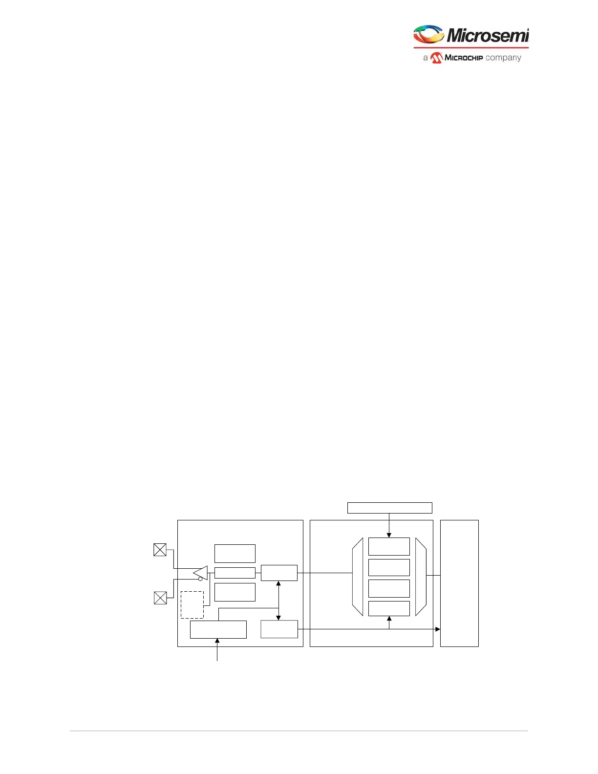
3.1.2 Transmitter
The transmitter takes parallel data from the FPGA fabric through the PCS-fabric interface block and
gearing logic. The data passes through the PMA-PCS interface to the serializer to create a high-speed
serial data stream using the serial clock provided from the transmit PLL. The transmitter portion of the
PMA includes the transmitter serializer and the transmitter buffer as shown in the following figure.
Figure 6 • Transceiver Transmitter
Transmit
PCS/
Fabric
Interface
Transmit PMA
PCIe Sub-System (PCIESS)
Transmit PCS
Transmit PLL
8b10b
Encoder
64b/6xb
Encoder
PCIe/PIPE
Pre-/Post-
Emphasis
Serializer
PCS
Divider
Out of Band
Electrical
Idle
PMA Only
÷ 1, 2, 4, 8, 11
XCVR_TXP
XCVR_TXN
PCIe
Rx
Detect