Debug and Testing
Microsemi Proprietary and Confidential UG0677 User Guide Revision 9.0 124
7.3 Dynamic Reconfiguration Interface
The dynamic reconfiguration interface (DRI) is used with PolarFire transceiver to access the memory
map of the transceiver blocks. DRI is an APB slave that allows global access to all transceiver lanes,
PCIe blocks, transmit PLLs, and FPGA PLLs. The DRI allows changing key features of the transceiver
before and during operation. The DRI connectivity is dedicated within the device requiring no FPGA
fabric routing. For more information about DRI, see UG0725: PolarFire FPGA Device Power-Up and
Resets User Guide and UG0922: PolarFire FPGA Dynamic Reconfiguration Interface User Guide (to be
released). For information about design targeted configuration, see Transceiver Initialization Data,
page 107.
Care must be exercised when using the DRI to alter transceiver settings as changes to the factory
settings can cause undesired results.
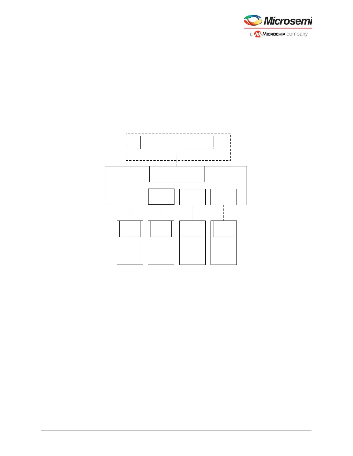
Figure 101 • PF_DRI Example
Note: For implementation example, see AC475: PolarFire FPGA Dynamic Reconfiguration Interface
Application Note.
Note: ** The PCIESS blocks do not connect directly to a DRI port, however, the associated XCVR LANE for
Quad0 must be connected to the DRI for dynamic control of the XCVR features used with PCIESS. The
PCIE[0:1] blocks have dedicated APB port for access to the register control within the PCIE subsystem.
XCVR**
PF_DRI
Component
DRI
DRI
DRI DRI
APB Mirrored Master
TXPLL
DRI DRI
TXPLL
DRI
CCC
DRI
Components
Soft Processor Subsystem
Master Example
Embedded
Wires