Functional Description
Microsemi Proprietary and Confidential UG0677 User Guide Revision 9.0 60
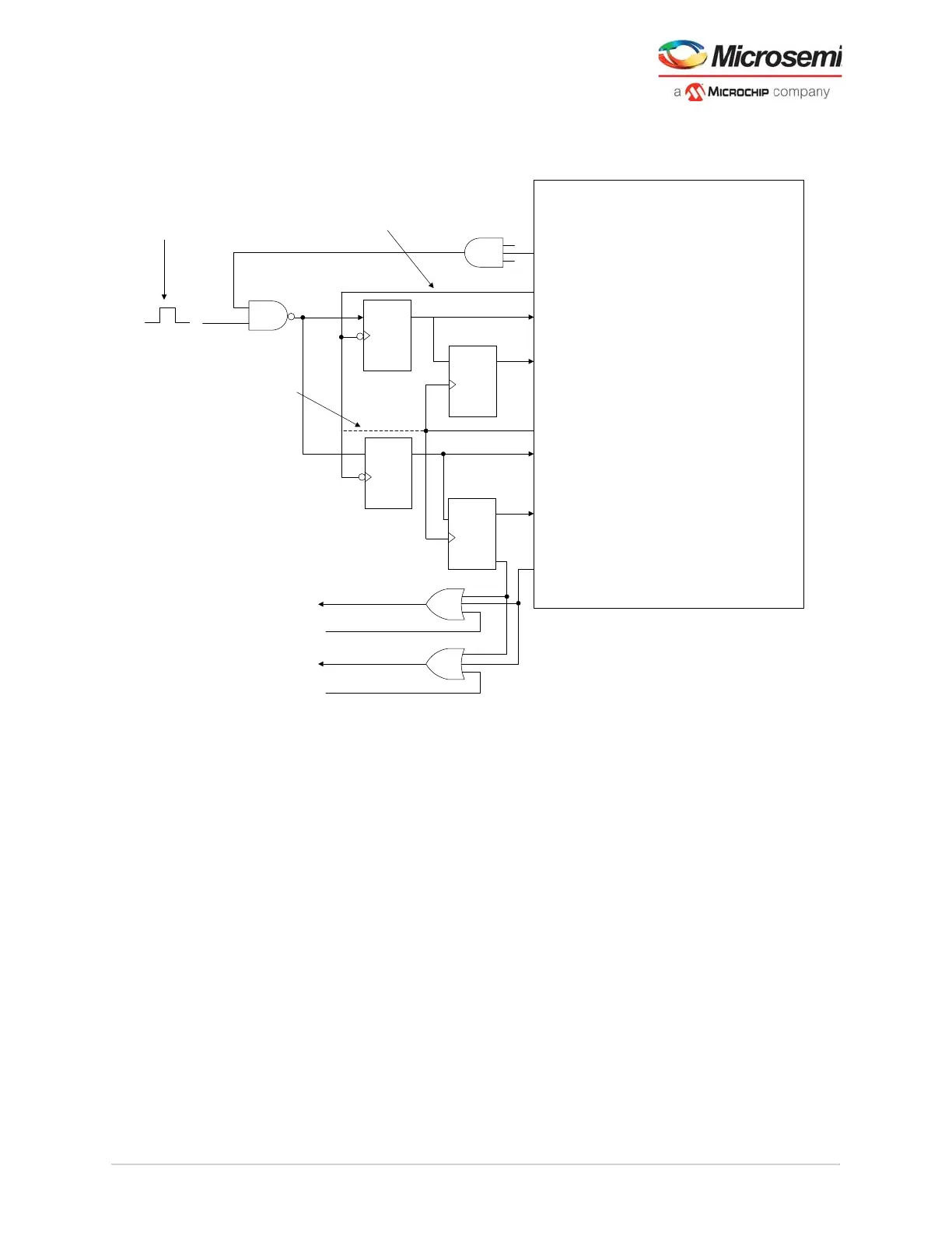
In these scenarios, the transceiver uses two PLLs with the same reference clock and a separate fabric
logic for reset of the TX lanes as shown in Figure 42, page 60.
Figure 42 • FPGA Logic For TX Alignment (5 to 8 Lanes)
The fabric reset logic per lane is provided by asserting the LANE#_PMA_ARST_N signal (where #
represents the lane to be reset). The RESETSEREN# register must be set to reset each lane. To achieve
proper skew alignment, the rising and falling edges of the RESETSER# signal must arrive at the
transceiver PMA lane pins within two high-speed bit clocks. This can be implemented by a known low-
skew internal clock signal using the global or local FPGA routing clocks to Flip-Flop inside the PCS. Any
arbitrary low-skew clock can be used as a reference clock to the transceiver Tx PLLs. The Tx_Align
pulse needs to be asserted for 16 clock cycles after the PLLs are locked and transmit lanes are
programmed with the same post-PLL divide factors. If this requirement is met, all of the TX lanes used for
the given transceiver port are aligned within 2 bit clock UIs.
PF_XCVR
Text
CLR
DQ
Text
CLR
DQ
Text
CLR
D
Q
CLR
D
Q
_
Q
_
Q
_
Q
_
Q
IMPORTANT: If Tx DIV2
mode is enabled, use
tx_fabric_clock for all
of these registers.
To Reset Tx Fabric Logic
To Reset Rx Fabric Logic
User Tx Reset
User Rx Reset
Neg Edge FF
Neg Edge FF
Tx_Align
NAND Gate
SET
SET
SET
SET
Pulsed high for at least 16
clock cycles – will cause Tx
alignment and Tx/Rx fabric
logic reset
Any low skew clock not from Tx or Rx SerDes
lane clocks that is at the same rate or slower
than the tx_fabric_clock (If Tx DIV2 mode
used, use tx_fabric_clock)
Tx PLL(s) Lock Signal(s)
Tx PLL Reference Clock
LANE#_PMA_ARST_N
(# = 0 for lane 0)
LANE#_TX_CLK (one per tx I/F for all lanes
chosen from any Tx lane)
LANE#_PMA_ARST_N (# = n for lane n)
LANE#_PCS_ARST_N
(# = n for lane n)
Various Resets from PCS Logic
(all include resets for initial start-up reset)
(for Rx, may also include CDR Lock(s))
LANE#_PCS_ARST_N
(# = 0 for lane 0)