Implementation
Microsemi Proprietary and Confidential UG0677 User Guide Revision 9.0 95
connected to the fabric resources. The dedicated CDR_REF_CLK_0/1 port must be connected to
the REF_CLK or REF_CLK_0/1 output of the PF_XCVR_REF_CLK block.
7. Select PCS-Fabric interface width from the GUI. This selection computes the FPGA interface
frequency. The FPGA interface frequency is calculated based on the transceiver data rate,
PCS-Fabric width, and the PCS settings/mode.
8. Click the GUI radio button to select the desired PCS mode. See Transceiver PCS Interface Modes,
page 23 for more information on PCS mode.
9. Select the desired interface clock options in the Interface Options GUI. See PCS/FPGA Fabric
Interface, page 48.
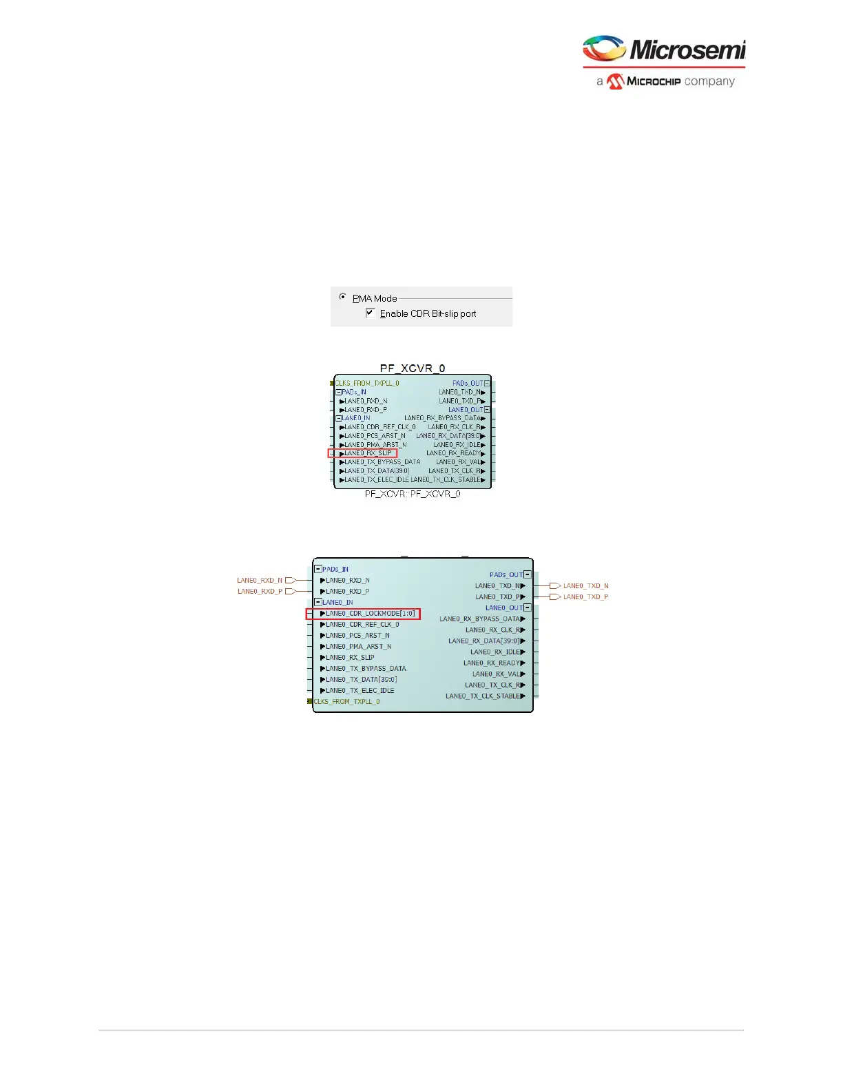
10. For PMA Only modes - CDR Bit-slip, select the Enable CDR Bit-slip port to add the
LANE#_RX_SLIP pin.
Figure 74 • PMA Mode—Enable CDR Bit-Slip Port
Figure 75 • XCVR Component With CDR Bit-Slip Port Enabled
Note: For information about RX_SLIP, see Bit Slip, page 11.
Figure 76 • XCVR Component With BMR Port Enabled
Note: For information about CDR_LOCKMODE pins, see burst mode receiver in CDR Options, page 10.
11. Select the Enable Dynamic Reconfiguration to add the LANE#_DRI_SLAVE pins. See Dynamic
Reconfiguration Interface, page 124 for usage details.