Functional Description
Microsemi Proprietary and Confidential UG0677 User Guide Revision 9.0 11
When BMR mode is selected, LANE_X_CDR_LOCKMODE[1:0] are exposed for CDR mode control. The
following table lists the value and the description of the CDR lock mode control bits.
For detailed CDR specifications, see DS0141: PolarFire FPGA Datasheet. For application example and
implementation details, see DG0841: PolarFire Burst Mode Receiver Demo Guide.
Lock to Data with 2X Gain: This transceiver option is used to implement the fast clock-data recovery
when incoming data streams such as stressful SDI patterns require high gain to quickly phase lock to the
incoming pattern. This mode produces faster lock times than that of normal lock-to-data mode.
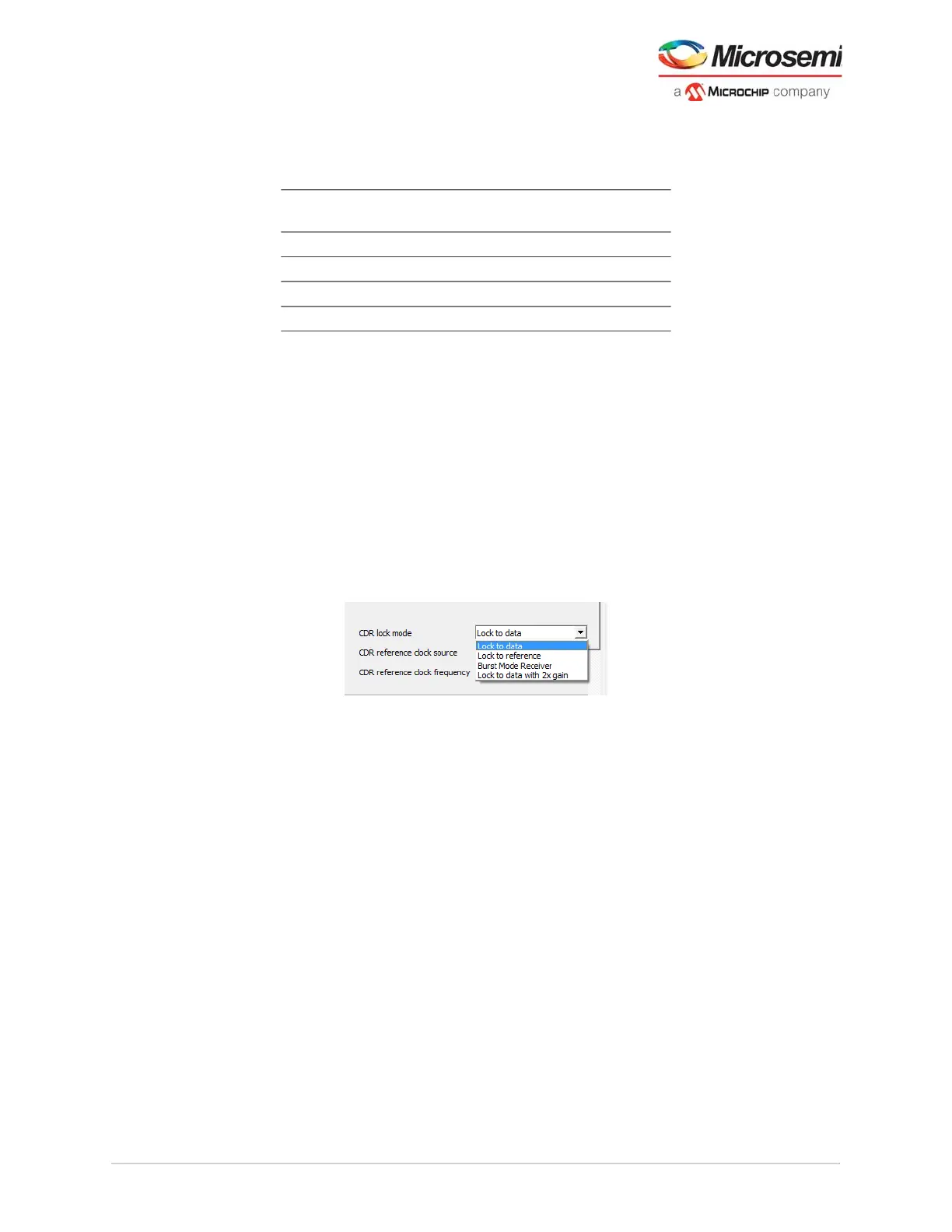
The following figure shows the CDR lock mode options.
Figure 5 • CDR Lock Mode Options
3.1.1.7 Bit Slip
The deserializer has a bit-slip feature for word alignment. In this mode, the CDR slips to the next bit from
the deserializer. This feature helps with building word-alignment logic in the fabric. It is not used with the
built-in 8b10b PCS core but is available for PMA only applications using fabric-based alignment. This
feature adjusts the alignment of the deserialized word by 1-bit in either direction when the bit-slip feature
is active, reducing the uncertainty by ensuring deterministic latency. This feature is supported by the
transceiver configurator. The configurator enables this RX_SLIP input port. This port requests the
transceiver CDR lane slip the parallel boundary by 1-bit.
In PMA mode applications, the RX_BIT_SLIP port is exposed on the block for the fabric to access. The
RX_BIT_SLIP rising edge requests Rx data path slip relative to the RX_CLK by 1-bit (UI) using
handshaking between RX_BIT_SLIP and RX_VAL. The handshake works as follows:
• Fabric must wait for RX_VAL = 1. Then RX_BIT_SLIP may be asserted to initiate slip.
• XCVR responds by lowering RX_VAL to 0.
• Fabric then lowers RX_BIT_SLIP.
• XCVR completes the slip and the RX_VAL is assigned to 1 synchronously with respect to RX_CLK
rising edge.
3.1.1.8 Receive PCS Divider
The PCS divider divides the bit-rate clock from the CDR PLL to a lower rate for use in the receive PCS.
The PMA sends parallel data from the de-serializer up to 40-bits wide. This divider also sets the width of
the parallel data provided to the PCS to 8, 10, 16, 20, 32, 40, 64, or 80 bits. The Libero transceiver
configurator sets the divider based on the data rate and ultimate fabric interface width.
Table 2 • CDR Lock Mode Values
LANE_X_CDR_LOCKMODE[1:0]
Values Mode
2’b00 Not used
2’b01 High gain
1
1. High Gain mode is used during Preamble/delimiter detection
phase to fast phase lock to the incoming RX data. This mode may
generate additional clock jitter on the recovered clock. Once the
preamble/de-limiter is detected, it is recommended to switch to
normal CDR mode to minimize jitter.
2’b10 Lock to reference
2’b11 Normal Mode
2
2. This is used when payload is received form burst mode receiver.