Functional Description
Microsemi Proprietary and Confidential UG0677 User Guide Revision 9.0 34
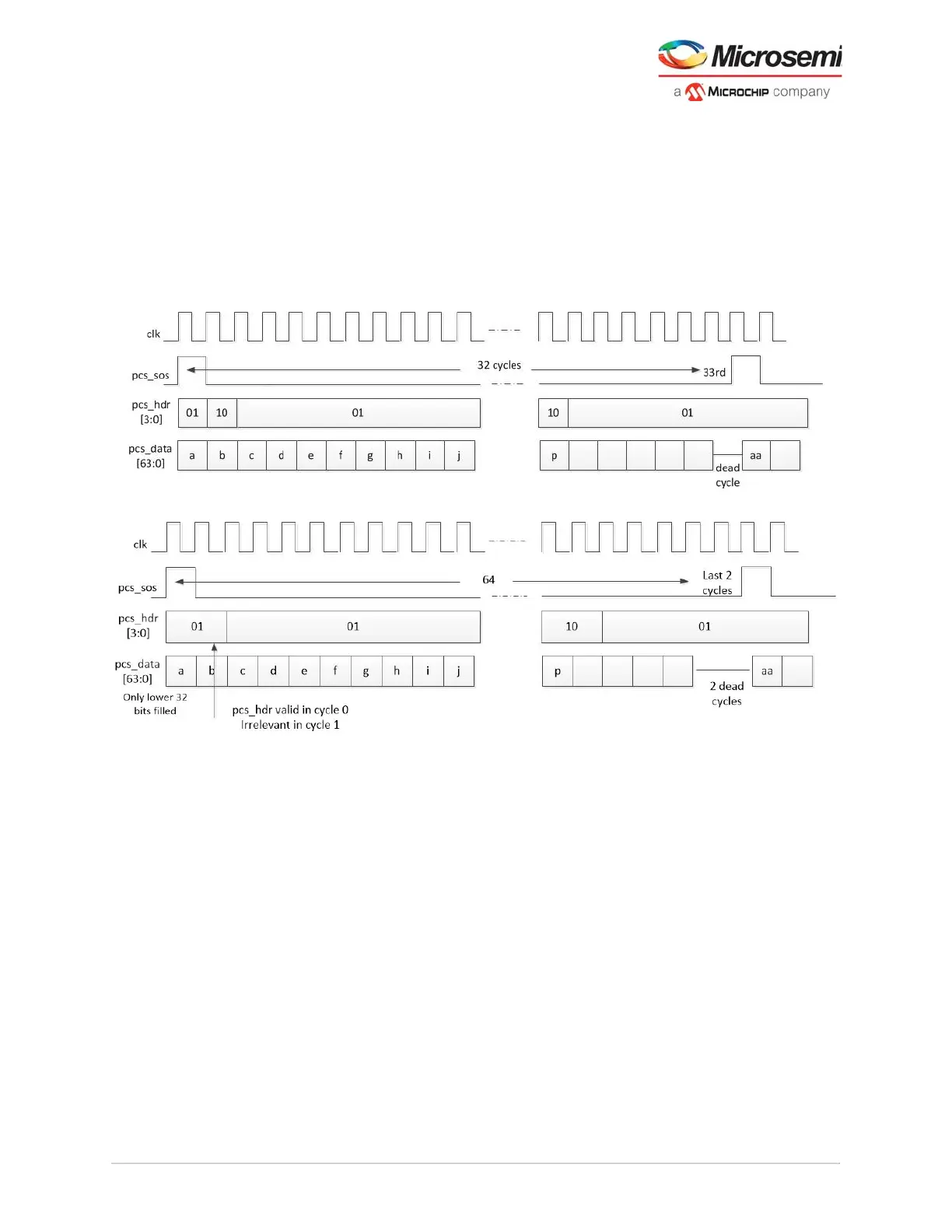
3.3.2.4 64b66b Transmit
In the transmit direction, the encoded 64-bit blocks are applied to PCS data from the fabric along with the
sync headers. When the 64-bit symbol is a control block, like Idle, Start or Terminate, then
pcs_hdr[1:0]=0b10. Otherwise, pcs_hdr[1:0]=0b01. The timing signal pcs_sos, indicates the sequence
boundaries. The sequence boundaries differ for 32-bit and 64-bit interfacing as shown in the following
figures. The configuration includes the scrambling of the data within the 64-bit blocks. Scrambling is done
in accordance with IEEE 802.3.
The transmit gearbox produces 32-bits to the PMA on each clock beat where the data is converted to
serial form and sent out to the link partner
Figure 20 • 64b66b Transmit Sequence For 64-Bit Interface
Figure 21 • 64b66b Transmit Sequence For 32-Bit Interface