Functional Description
Microsemi Proprietary and Confidential UG0677 User Guide Revision 9.0 20
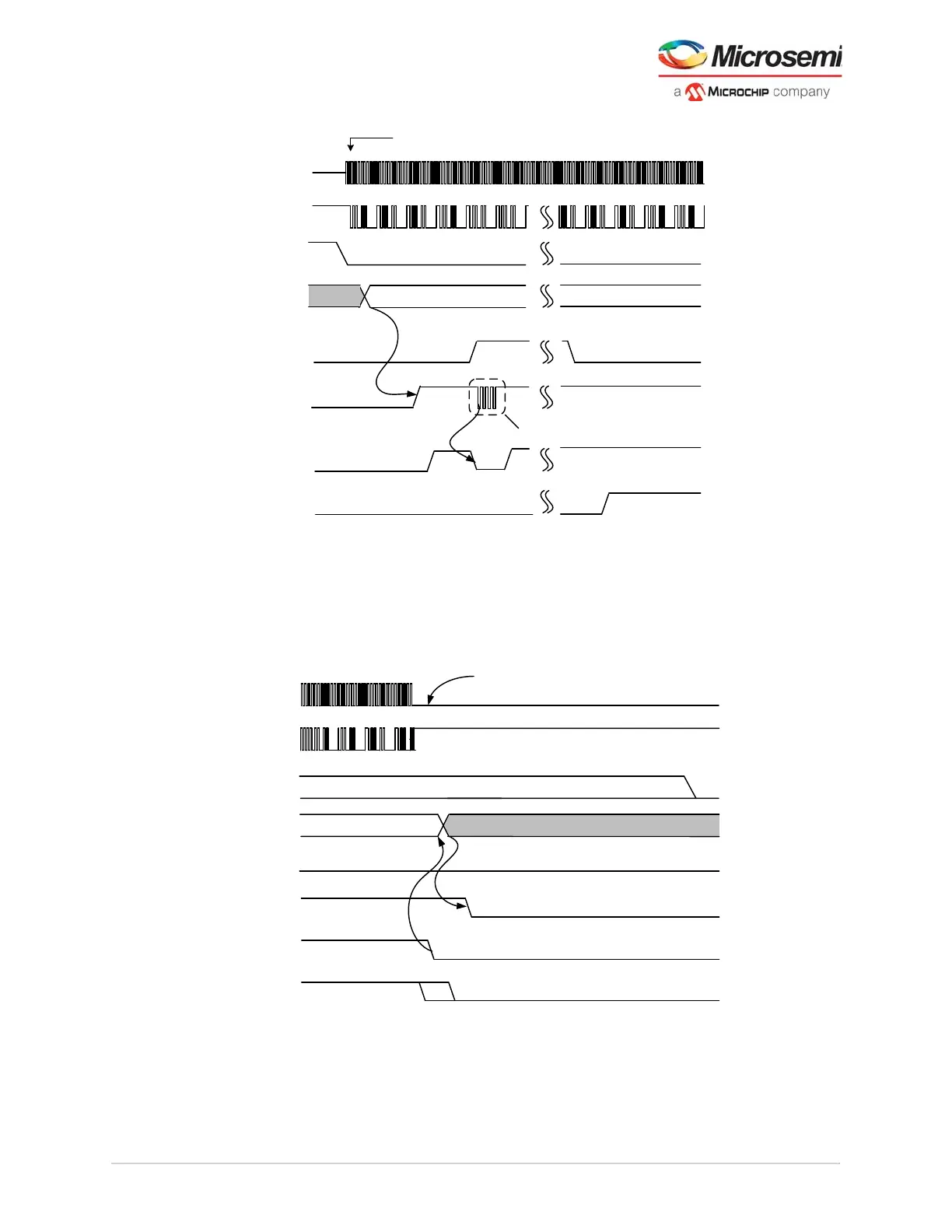
Figure 12 • First Lock Calibration Waveform
During data transmission if the serial link is disrupted due to lack of activity detected by the Fine Lock
LANE#_RX_READY =0 and toggling of the LANE#_RX_IDLE output signal, the ERM handles a switch
over of the CDR from LOCK2DATA to LOCK2REF as shown in following figure. The ERM manages this
mode until the data stream is re-established or the transceiver is placed into reset.
Figure 13 • Disruption of Serial Rx Data Stream
LTD
Cannot stop transmitting until RX_VAL rises
Tx Source device powered-up and transmitting
Glitches on RX_IDLE is expected for incoming traffic > 5Gbps
LANE#_RX_READY
(Rx Fine Lock)
LANE#_RXD[P-N]
LANE#_RX_IDLE
CDR Status(Internal)
LANE#_CALIBRATING
LANE#_RX_VAL
LTR= Lock to Reference clock
LTD= Lock to Data
LTR
LANE#_RX_READY_CDR
Calibration takes control of
RxPLLfor short period of time
LANE#_LOS
Transmitted signal is DC. This condition can be detected within 100uS
Glitches on RX_IDLE is expected for incoming traffic > 5Gbps
RX_VAL may fall earlier due to 64b6xb framing errors or assetion of PCS_ARSTN
from FPGA fabric.
LANE#_RXD[P-N]
LANE#_RX_IDLE
CDR Status(Internal)
LANE#_RX_VAL
LTR= Lock to Reference clock
LTD= Lock to Data
LTR
LTD
LANE#_CALIBRATING
LANE#_RX_READY_CDR
LANE#_RX_READY
(Rx Fine Lock)
LANE#_LOS
Do Not Care