Functional Description
Microsemi Proprietary and Confidential UG0677 User Guide Revision 9.0 9
3.1.1.2 Loss of Signal Detect (LOS)
Loss of signal (LOS) detection is included within the receiver path. The LOS circuitry detects the initial
incoming signal determining a valid input (electrical RX_IDLE=0) for clock-data recovery operations. The
LOS peak detection captures the most positive and negative points of the input signal and compares the
amplitude to a limit set by the user. See Loss-of-Signal Detector, page 111. The performance of the
physical peak detector is limited by the bandwidth of the input signal. The LOS detection works for rates
5 Gbps and less and may not be suitable for all protocols or data patterns. For conditions outside the
range of the LOS operation, see Enhanced Receiver Management, page 16.
3.1.1.3 Continuous-Time Linear Equalizers (CTLE)
The CTLEs equalize a lane’s low-pass response to compensate for high-frequency losses in that lane,
thereby improving the quality of the received signal. This circuit can be adjusted to compensate for any
physical lane mismatches.
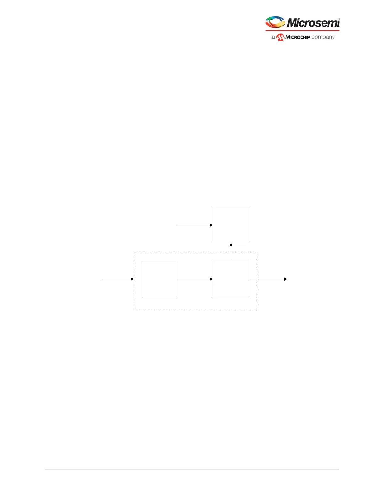
There are two transparent stages of CTLE and a separate pair of stages for the decision feedback
equalizer (DFE)/eye monitor receive path. The input signal path (Figure 4, page 9) is conditioned by
tuning the incoming signal allowing the user to observe the effects of the tuning. The DC gain and peak
bandwidth of each stage is selected with Libero; CTLE settings can be selected based on DC gain,
peaking frequency, and AC gain or with an auto adaptive setting through the Libero transceiver interface
configurator. The automatic or adaptive mode uses internally generated settings to the physical channels
for lane optimization.
Figure 4 • Input Signal Path
3.1.1.4 Decision Feedback Equalizer
In the receiver front end, an optionally enabled 5-tap decision feedback equalizer (DFE) is available to
equalize the lane response in conjunction with the CTLE. The DFE allows better compensation of
transmission channel losses than a linear equalizer of CTLE, by providing a closer adjustment of filter
parameters. The tap values of the DFE are the coefficients of this filter that are set by the adaptive
algorithm.
The DFE mitigates lane noise or inter-symbol interference (ISI) caused by reflections or cross-talk
without amplifying the high-frequency noise within the data. The DFE-based operation uses current bit
information to cancel ISI for the following bit through a feedback mechanism, allowing the following bits to
be correctly sampled. Using taps to delay and multiply the symbols, the DFE effectively cancels out
interference on the analog signal. Similar to the CTLE operation, the DFE has an automatic mode. When
the DFE is used in automatic mode, the CTLE can be in automatic mode as-well.
The operation is nonlinear, allowing it to overcome the notch response that the CTLE cannot perform.
The DFE also includes an automatic calibration that finds the best possible tuning to match the
transceiver lane to the system channel.
Receiver Input
CTLE
DFE + CDR
Eye
Monitor
Deserializer
Adaptive Tuning
SmartDebug
Via JTAG