Functional Description
Microsemi Proprietary and Confidential UG0677 User Guide Revision 9.0 17
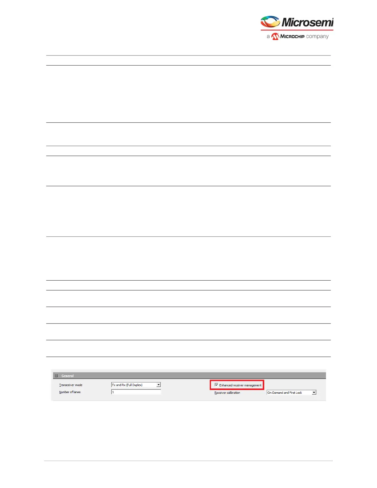
Figure 8 • Enhanced Receiver Management in XCVR Configurator
The operation ERM relies on the transceiver configurator settings to determine the selected calibration
requirements as shown in the following figure. The transceiver lane calibration options are selected with
the PolarFire transceiver configurator. See Receiver Calibration, page 12 for more information.
LANE#_LOS Input LANEx_LOS input which may be asserted from an external source such-as
optical SFP during no-signal condition as a means of preventing entry to lock-
to-data. This input should be used to control application scenarios where the
incoming data stream has enough activity to trigger the LANE#_RX_IDLE but
lacks enough transitions to lock the RXPLL. LOS=0 (de-assertion) should
happen when valid serial data is applied at the RxP/N inputs of the receiver.
LOS=1 assertion must happen prior to the ERM's entry to lock-to-data,
otherwise the assertion does nothing.
LANE#_CALIB_REQ Input Active-high input signal used to request an On-Demand calibration.
LANE#_CALIB_REQ is edge triggered not level. User must clear and re-
assert the CALIB_REQ for trigger on-demand calibration request.
LANE#_CALIBRATING Output Output signal that will go high to indicate that the DFE/CDR is calibrating.
LANE#_RX_VAL Output Indicates CDR fine lock and ERM managed operations complete. See
Transceiver PCS Interface Modes, page 23 for more information.
1 – indicates Fine Lock is asserted, and recovered data is valid.
0 – indicates Fine Lock is de-asserted and recovered data is invalid.
LANE#_RX_IDLE Output Indicates activity on the receiver inputs (RXD[P:N]). For ≤ 5Gbps, active-low
(RX_IDLE=0 indicates activity). For >5G bit rates, this signal may not be
accurate indicator of data activity. It may toggle or be high although valid
signal is applied at the receiver. This signal is exposed for debugging
purposes only, for example, detection of signal when RxPLL is in lock2ref
mode. See Figure 12, page 20, Figure 13, page 20, Figure 14, page 21, and
Figure 15, page 22.
LANE#_RX_READY Output Indicates CDR fine lock completion. See Transceiver PCS Interface Modes,
page 23 for more information.
1 – Fine lock is asserted (that is, RxPLL is locked to incoming data within
± 4000 ppm of the LANE#_TX_CLK_{G,R} frequency).
0 – Fine lock is de-asserted (that is. recovered clock is outside the ± 4000 ppm
of the REFCLK frequency).
LANE#_RXD[P:N] Input Differential pair of serial data inputs.
LANE#_DATA_EYE_
CALIBRATION
Input Active-high input signal (Asynchronous signal) to request Data Eye clock
centering recalibration.
LANE#_DFE_COEFF_
CALIBRATION
Input Active -high input signal (Asynchronous signal) to request Incremental DFE
Coefficient recalibration.
LANE#_DATA_EYE_
CALIBRATION_DONE
Output Data Eye clock centering recalibration request handshake signal. This signal
goes high when the Data Eye clock centering calibration is done.
LANE#_DFE_COEFF_
CALIBRATION_DONE
Output Incremental DFE coefficient recalibration request handshake signal. This
signal goes high when the Incremental DFE coefficient recalibration is done.
Table 4 • ERM Ports
Name Direction Description